a cutting tool

A technology of cutting tools and cutting blades, applied in cutting blades, tools for lathes, turning equipment, etc., can solve the problems of blade four-point contact failure, complex structure, poor reliability, etc., achieve reliable positioning, improve machining accuracy, The effect of easy disassembly and assembly

Active Publication Date: 2017-03-29
ZHUZHOU CEMENTED CARBIDE CUTTING TOOLS CO LTD
View PDF2 Cites 0 Cited by
  • Summary
  • Abstract
  • Description
  • Claims
  • Application Information

AI Technical Summary

Problems solved by technology

For example, a tool produced by ISCAR (Iscar, one of the largest manufacturers of metal cutting tools in the world) contains a wedge that can move freely with the direction of cutting force, and the wedge is closely attached to a positioning side of the tool groove to ensure The four-point contact of the blade, but the wedge is movable and is not connected with the tool, so there is a risk in some occasions of cutting; Chinese patent documents CN1267222C and CN1267223C disclose two kinds of tool holder structures, and these two kinds of tool holder structures Both contain a blade mounting plate, and the slot structure on the blade mounting plate endows one side positioning surface of the knife groove with an elastic deformation function to realize the four-point contact positioning of the cutting blade, but the structure of the blade mounting plate is relatively complicated, and the mounting plate The slot structure on the upper part makes the elastically deformed part relatively fragile, and the distance between the two points provided by the elastically deformed side in the patent CN1267223C is too close, the reliability is poor, and it is easy to cause the four-point contact failure of the blade

Method used


Image

  • a cutting tool
  • a cutting tool
  • a cutting tool

Examples


Embodiment Construction

[0024] The present invention will be further described in detail below in conjunction with the accompanying drawings and specific embodiments.

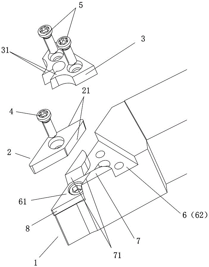
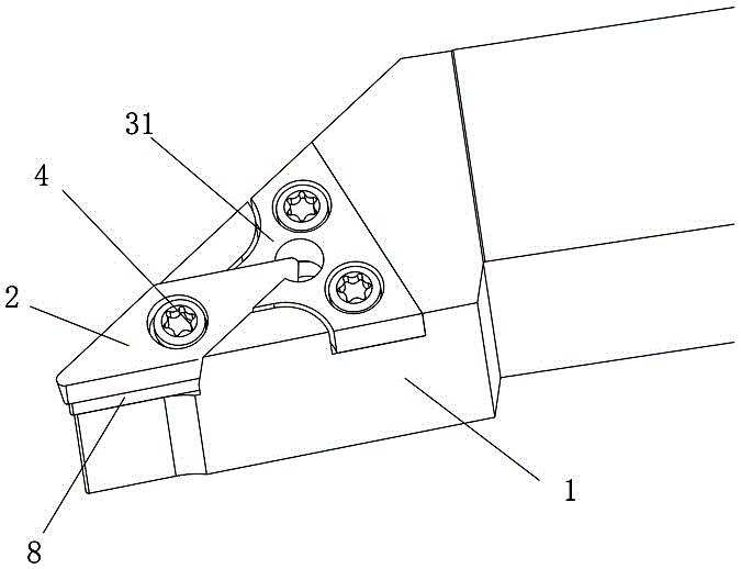
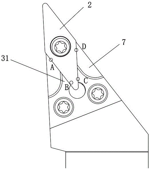
[0025] Figure 1 to Figure 4 Shown is an embodiment of the cutting tool of the present invention, the cutting tool includes a cutter body 1, a cutting blade 2 and a positioning plate 3, the head of the cutter body 1 is provided with a sipe 6, and the sipe 6 includes a communicating blade receiving groove 61 and the positioning plate accommodation groove 62, the cutting blade 2 is installed in the blade accommodation groove 61 through the first fastening screw 4, the positioning plate 3 is installed in the positioning plate accommodation groove 62 through the second fastening screw 5, and the positioning plate 3 is provided with An elastic positioning claw 31 that is in contact with one of the side positioning surfaces 21 of the cutting blade 2 and can be elastically deformed. A positioning flank plate 7 that is in contact with the sid...


PUM


Abstract

The invention discloses a cutting tool which comprises a tool body, a cutting blade and a positioning plate. A tool groove is formed in the head portion of the tool body and comprises a blade accommodating groove and a positioning plate accommodating groove which are communicated with each other, the cutting blade is installed in the blade accommodating groove through a first fastening screw, the positioning plate is installed in the positioning plate accommodating groove through a second fastening screw, an elastic positioning claw matched with one side positioning face of the cutting blade in a contact mode and capable of elastically deforming is arranged on the positioning plate, and a positioning side web plate matched with the side positioning face in a matched mode is arranged in the cutter groove. When the first fastening screw is fastened, the elastic positioning claw and the positioning side web plate matched with the same side positioning face of the cutting blade in the contact mode jointly press the cutting blade. The cutting tool has the advantages of being simple in structure, convenient to dismount, high in positioning accuracy, capable of improving the part machining accuracy and the like.

Description

technical field [0001] The invention relates to the field of metal cutting, in particular to a cutting tool. Background technique [0002] In the field of metal cutting, the positioning of the insert of the cutting tool in the sipe is usually achieved by contacting the side of the insert with the side positioning surface of the sipe. When the blade is installed on the cutter body groove by the action of the compression screw, the side positioning surface of the blade groove will be partially deformed to ensure contact with the side of the blade. Positioning is often reflected in three-point contact, and in the field of metal turning finishing, V-shaped or D-shaped inserts with sharp tips are often used, so this three-point positioning tool structure shows defects, because the cutting insert When participating in cutting, under the impact of cutting force, the blade is prone to deflection due to the instability of the three-point contact, which affects the machining dimensio...

Claims


Application Information

Patent Timeline
Patent Type & Authority Patents(China)
IPC IPC(8): B23B27/16
CPCB23B27/1644B23B2205/04B23B2205/12
Inventor 彭震王云志王春秀吴敏
Owner ZHUZHOU CEMENTED CARBIDE CUTTING TOOLS CO LTD
Why Eureka
Try Eureka