Production equipment of autoclaved aerated concrete blocks

A technology for concrete blocks and production equipment, which is applied in the direction of clay preparation device, mixing operation control, mixing operation control device, etc., which can solve the problems of low intelligence, low production efficiency, low efficiency, and scattered assembly, and improve intelligence. degree, convenient speed control, and the effect of improving production efficiency

Inactive Publication Date: 2015-08-19
HANCHUAN XINXIN TECH
View PDF0 Cites 9 Cited by
  • Summary
  • Abstract
  • Description
  • Claims
  • Application Information

AI Technical Summary

Benefits of technology

The technical effect of this new technology described by Cement Company relating to an improved method for producing self-cured foam blocks (SCBs) was achieved when they were produced without requiring manual measurement or adjustment during manufacturing process. This resulted in more accurate weightings compared to previous methods while also enhancing their durability against impact damage from external factors such as rainwater. Overall, these improvements led to better quality products being made at lower cost than current processes.

Problems solved by technology

The technical problem addressed by this patented technology relates to improving the accuracy and productivity of producing autocallued aerated concretes with multiple functions such as making it easier for workers to assemble them themselves or create more efficient products due to its unique design that allows for precise measurement without requiring manual labor.

Method used


Image

  • Production equipment of autoclaved aerated concrete blocks
  • Production equipment of autoclaved aerated concrete blocks

Examples


Embodiment Construction

[0014] The technical solutions in the embodiments of the present invention will be clearly and completely described below in conjunction with the accompanying drawings in the embodiments of the present invention. Obviously, the described embodiments are only a part of the embodiments of the present invention, rather than all the embodiments. Based on the embodiments of the present invention, all other embodiments obtained by those of ordinary skill in the art without creative work shall fall within the protection scope of the present invention.

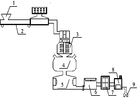
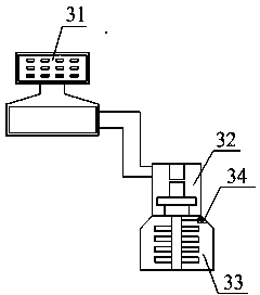
[0015] See Figure 1-2 , The present invention provides a technical solution: an autoclaved aerated concrete block production equipment, including a feed port 1, a conveyor belt 2, a crushing mixer 3, a feeding mixing chamber 4, a mobile pouring chamber 5, a hardening curing chamber 6, a three-dimensional The cutting machine 7, the sealed autoclaved cavity 8 and the conveying hanging clamp tool 9, the feed port 1 is set at the front end ...


PUM


Abstract

The invention discloses production equipment of autoclaved aerated concrete blocks, comprising a feed inlet, a conveyer belt, a crushing stirrer, a feeding mixing chamber, a moving pouring chamber, a hardening curing chamber, a solid cutting machine, a sealed autoclaving chamber and a conveying hanging tool. The crushing stirrer is connected between the conveyer belt and the feeding mixing chamber. The feeding mixing chamber is connected between the crushing stirrer and the moving pouring chamber. The moving pouring chamber is connected between the feeding mixing chamber and the hardening curing chamber. The hardening curing chamber is connected between the moving pouring chamber and the solid cutting machine. An auto-metering display screen helps improve precision of material weighing; a grinding crushing chamber helps improve viscosity of prepared slurry; a speed governor helps improve intelligence level and production efficiency.

Description


Claims


Application Information

Patent Timeline
Owner HANCHUAN XINXIN TECH
Why Eureka
Try Eureka