Screen frame positioning equipment and screen frame positioning method

A technology for positioning equipment and screen frames, applied to screen printing machines, rotary printing machines, printing, etc., can solve problems such as inaccurate positioning, screen frame installation deviation, and low accuracy, and achieve convenient installation and disassembly, accurate overprinting, The effect of precise positioning

Inactive Publication Date: 2015-08-19
厦门福源智印科技有限公司
View PDF6 Cites 1 Cited by
  • Summary
  • Abstract
  • Description
  • Claims
  • Application Information

AI Technical Summary

Problems solved by technology

[0003] The purpose of the present invention is to provide a new screen frame positioning method to solve the problems of troublesome screen frame overprinting on the market, low efficiency, heavy objects, inaccurate positioning, low accuracy, and screen frame installation deviation.

Method used


Image

  • Screen frame positioning equipment and screen frame positioning method
  • Screen frame positioning equipment and screen frame positioning method
  • Screen frame positioning equipment and screen frame positioning method

Examples


Embodiment 1

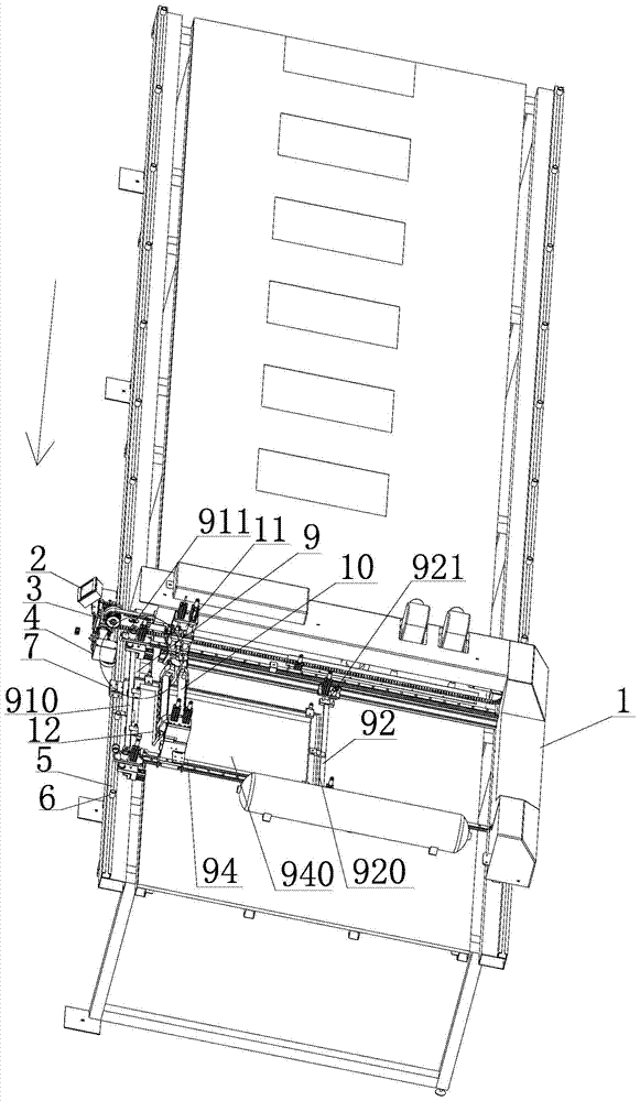
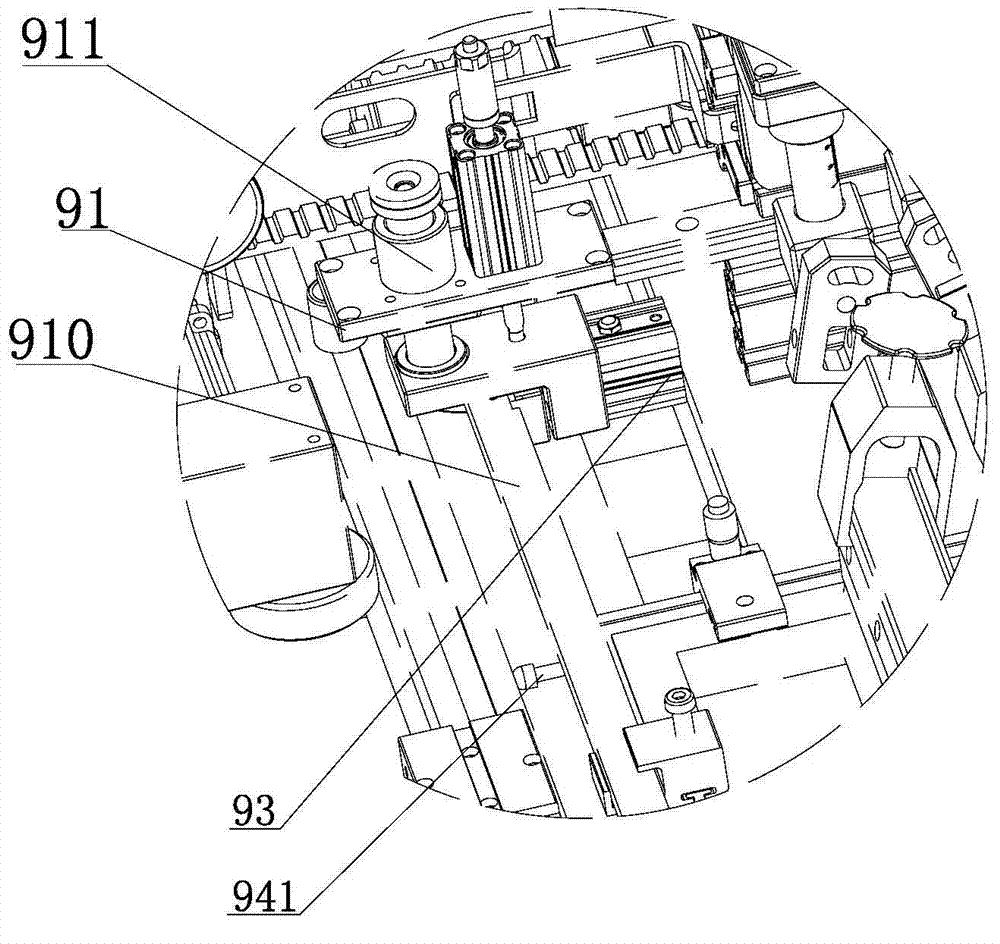
[0033] Example 1: See Figure 1 to Figure 3 , a method for positioning a screen frame, comprising the steps of:

[0034] (1) The front frame crossbeam 910 descends under the action of the front crossbeam lifting cylinder 911, and the crossbeam 10 descends with the screen frame 94;

[0035] (2) The front beam 910 of the screen frame is pushed under the action of the front and rear movement cylinder 911 of the front beam until the frame positioning pin 941 on the screen frame 94 is tightly attached to the guide rail 5. This step is referred to as "forward operation", here Forward movement refers to the direction of the front end of the screen frame;

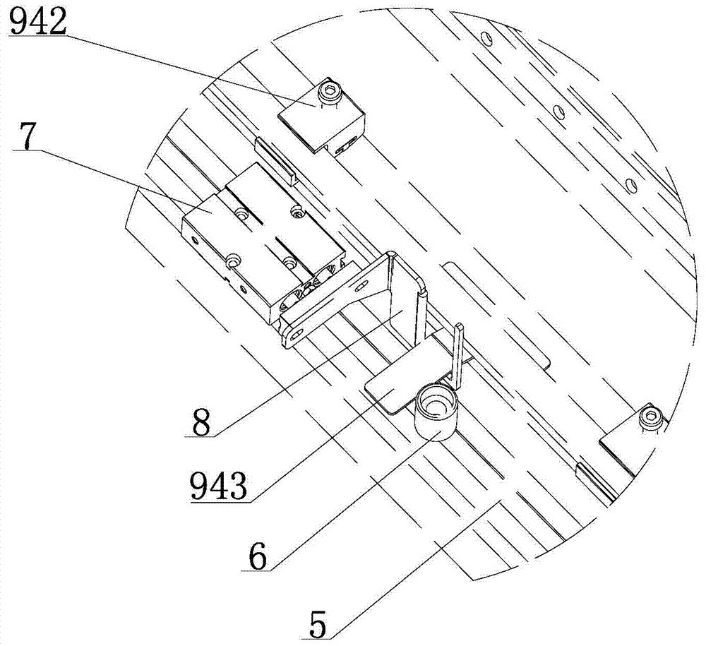
[0036] (3) The double-rod left and right positioning cylinder 7 pushes the positioning push block 8, and the positioning push block 8 pushes the T-shaped iron 943 on the screen frame to move to the right until the T-shaped iron 943 is close to the positioning column 6. This step is referred to as "moving to the right". Operation"...

Embodiment 2

[0039] Example 2: see Figure 1 to Figure 3 , a method for frame positioning, comprising the steps of:

[0040] (1) The front frame crossbeam 910 descends under the action of the front crossbeam lifting cylinder 911, and the crossbeam 10 descends with the screen frame 94;

[0041] (2) The double-rod left and right positioning cylinder 7 pushes the positioning push block 8, and the positioning push block pushes the T-shaped iron 943 on the screen frame to move to the right until the T-shaped iron 943 is close to the positioning column 6, which is "right shift operation";

[0042] (3) The front frame crossbeam 910 is pushed under the action of the front and rear movement cylinder 911 until the screen frame positioning pin 941 on the screen frame 94 is tightly attached to the guide rail 5, which is "forward operation";

[0043] (4) The rear screen frame crossbeam 920 descends under the effect of the rear crossbeam lifting cylinder 921, and the crossbeam 10 descends together with...


PUM


Abstract

The invention provides screen frame positioning equipment and a screen frame positioning method. The screen frame positioning equipment comprises a base, a worktable, a conveying device, a driving device, guide rails, positioning pillars, a dual-rod left-and-right positioning cylinder, a positioning push block, an artificial screen frame positioning device, a cross beam, a cross beam cylinder and a scraper assembly. The screen frame positioning equipment and the screen frame positioning method have the benefits that the mounting and dismounting are convenient, and a screen frame does not need to be changed; the safety is achieved, the manual positioning can be simulated, and the positioning is accurate; after power failure, the manual operation can be automatically converted; panels are called out, the overprinting is accurate, and the efficiency is high.

Description

technical field [0001] The invention relates to a screen frame positioning device, in particular to a screen frame positioning device and a method thereof. Background technique [0002] The overprinting of screen frames on the market is very troublesome, low efficiency, heavy objects, inaccurate positioning, low accuracy, and deviation of screen frame installation. The current positioning of the screen frame is often achieved in one step through motor control. Therefore, the accuracy of motor displacement is high, but the positioning effect in practical applications is poor. Contents of the invention [0003] The purpose of the present invention is to provide a new screen frame positioning method to solve the problems of troublesome screen frame overprinting, low efficiency, heavy objects, inaccurate positioning, low precision, and screen frame installation deviation in the market. [0004] At the same time, the invention also provides a screen frame positioning device ma...

Claims


Application Information

Patent Timeline
Patent Type & Authority Applications(China)
IPC IPC(8): B41F15/36
Inventor 宋其斌
Owner 厦门福源智印科技有限公司
Why Eureka
Try Eureka