Gap adjusting component and electric lifting adjusting device of automobile seat with gap adjusting component

A technology of clearance adjustment and lifting adjustment, which is applied in electromechanical devices, vehicle seats, movable seats, etc., can solve the problems of many parts and high cost, and achieve the effect of cost reduction, number of parts reduction, and elimination of axial clearance

Active Publication Date: 2015-08-19
KEIPER (CHANGSHU) SEATING MECHANISMS CO LTD
View PDF9 Cites 5 Cited by
  • Summary
  • Abstract
  • Description
  • Claims
  • Application Information

AI Technical Summary

Problems solved by technology

[0003] One of the technical problems to be solved by the present invention is to provide a gap adjusting member with few parts and low cost in order to solve the problems of many parts and high cost in the gap adjustment device of the existing car seat transmission mechanism

Method used


Image

  • Gap adjusting component and electric lifting adjusting device of automobile seat with gap adjusting component
  • Gap adjusting component and electric lifting adjusting device of automobile seat with gap adjusting component
  • Gap adjusting component and electric lifting adjusting device of automobile seat with gap adjusting component

Examples


Embodiment 1

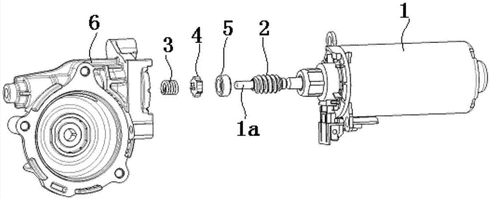
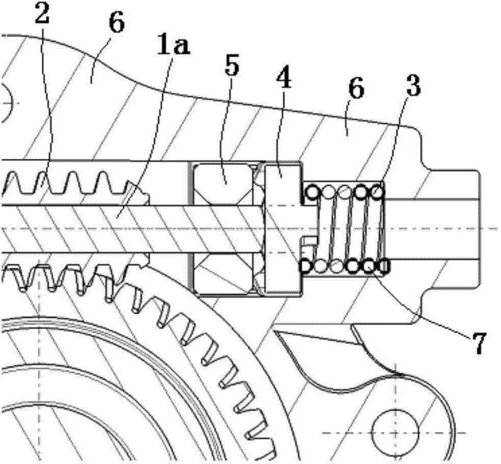
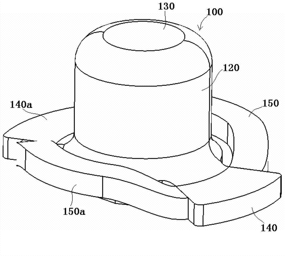
[0041] see image 3 and Figure 4 , the gap adjustment member 100 shown in the figure is a plastic part, which includes a cylinder part 120 with an inner cavity 110, one end of the cylinder part 120 is open, and the other end is provided with an axially restricting end wall 130, in the cylinder The wall of the inner chamber 110 of the body part 120 is provided with a straight exhaust groove 111 parallel to the axis of the barrel part 120 .

[0042] At one end of the cylinder part 120, there are two fan-shaped stoppers 140, 140a symmetrically arranged to limit the rotation of the gap adjustment member 100, and at one end of the cylinder part 120, two axial gap adjustment bellows are also symmetrically arranged. Edges 150, 150a, the two ends of each axial clearance adjusting corrugated edge 150, 150a are respectively connected with two stoppers 140, 140a, and at the same time, the inner edge of each axial clearance adjusting corrugated edge 150, 150a is not in contact with the ...

Embodiment 2

[0045] see Image 6 and Figure 7, the gap adjustment member 100' shown in the figure is a plastic part, which includes a cylinder part 120' with an inner cavity 110', one end of the cylinder part 120' is open, and the other end is provided with an axially restricting end wall 130 ′, an exhaust hole 131 ′ communicating with the inner chamber 110 ′ of the cylindrical portion 120 ′ is opened in the center of the axially restricting end wall 130 ′ of the cylindrical portion 120 ′.

[0046] One end of the cylinder part 120' is symmetrically provided with two fan-shaped stoppers 140', 140a' for restricting the rotation of the gap adjusting member 100', and two symmetrically arranged at one end of the cylinder part 120'. Axial gap adjustment corrugated edges 150', 150a', the two ends of each axial gap adjusting corrugated edge 150', 150a' are respectively connected with two stoppers 140', 140a', and each axial gap adjusting corrugated The inner edges of the sides 150', 150a' are n...


PUM


Abstract

The invention discloses a gap adjusting component which is a plastic piece and comprises a cylinder part with an inner cavity. A first end of the cylinder part is opened, and a second end of the cylinder part is provided with an axial limiting end wall. An axial gap adjusting corrugated edge is arranged at the first end of the cylinder part. The corrugate fluctuating direction of the axial gap adjusting corrugated edge is parallel to the axial direction of the cylinder part. After the gap adjusting component is applied to an electric lifting adjusting device of an automobile seat, the axial gap of an output shaft for driving a motor is eliminated through the deformation of the axial gap adjusting corrugated edge of the gap adjusting component, and the tolerance requirement of a reduction gearbox body and a worm is lowered. The gap adjusting component has the advantage that by means of the gap adjusting component, an adjusting spring, a wear-resistant gasket and an oil-contained bearing in the prior art are replaced to eliminate the axial gap, the number of parts is decreased, assembling is simplified, and cost is reduced. In addition, the gap adjusting component can be designed in a modularized mode.

Description

technical field [0001] The invention relates to the technical field of automobile seats, in particular to a component of a clearance adjusting device and an electric lift adjustment device for an automobile seat comprising the clearance adjusting component. Background technique [0002] The applicant for this patent submitted a utility model patent application for an electric lift adjustment device for automobile seats to the State Intellectual Property Office of China on January 6, 2011, which has now been authorized, and the authorization announcement number is CN202006739U. see figure 1 The axial clearance between the output shaft 1a of the driving motor 1 of the worm 2 and the reduction box 6 is adjusted by the adjustment spring 3, the wear-resistant gasket 4 and the oil bearing 5 installed on the end face of the worm 2 tail end. see figure 2 , the tail end of the worm 2 connected to the output shaft of the drive motor 1 is covered with an oil bearing 5, and its end f...

Claims


Application Information

Patent Timeline
Patent Type & Authority Applications(China)
IPC IPC(8): B60N2/16H02K7/10H02K7/116
CPCB60N2/166H02K7/10H02K7/1166
Inventor 庄伟清聂维钦黎其俊常健
Owner KEIPER (CHANGSHU) SEATING MECHANISMS CO LTD
Why Eureka
Try Eureka