Supercharge Your Innovation With Domain-Expert AI Agents!

Transmission mechanism of a wing of an orthopter

A technology of transmission mechanism and flapping wing aircraft, which is applied in the field of general aviation, can solve the problems that the advantages of flapping wing flight cannot be reflected, the essence of flapping wing flight is not well understood, and the aerodynamic advantages of flapping wing flight cannot be reflected, so as to achieve concealment Good effect, reduced flight resistance, wide application prospects

Active Publication Date: 2017-03-01
许允夫 +1
View PDF5 Cites 0 Cited by
  • Summary
  • Abstract
  • Description
  • Claims
  • Application Information

AI Technical Summary

Problems solved by technology

[0002] Nowadays, the world pays more attention to the development of orthopter. Many countries have developed various orthopeds, some of which imitate the flying methods of insects, and some imitate the flying methods of birds. However, due to various reasons, only Being able to imitate some of the functions and movements of the original creature does not fully reflect the advantages of flapping-wing flight. The main reason is that the essence of flapping-wing flight is not well understood, and it only imitates part of the original creature's movements one-sidedly. , like the robot bird developed by some institutions, it can only show that when the wings are raised, the outer wing section is bent downward. Although the flapping flight has been realized, it still cannot reflect the aerodynamic advantages of the flapping flight

Method used


Image

  • Transmission mechanism of a wing of an orthopter
  • Transmission mechanism of a wing of an orthopter
  • Transmission mechanism of a wing of an orthopter

Examples


Embodiment Construction

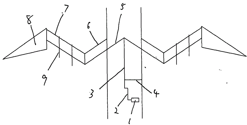
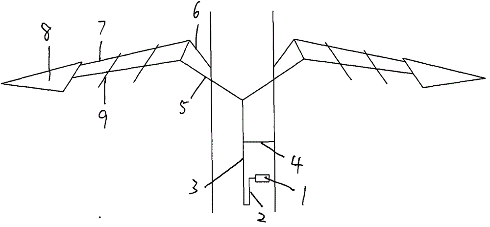
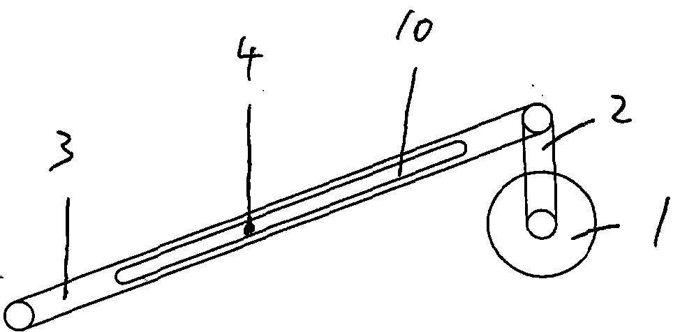
[0013] The transmission mechanism of the wing of orthopter is made of motor, crankshaft, connecting rod, stator, inner wing section skeleton, middle wing section skeleton and outer wing section. In the figure, the motor is connected to the crankshaft, and the crankshaft is connected to the connecting rod. There is a gap in the middle of the connecting rod. One end of the stator is fixed on the fuselage, and the other end passes through the gap in the middle of the connecting rod. One end inside the fuselage, the rear frame of the inner wing section passes through the fuselage outwards, and a point connected to the fuselage is used as a fulcrum, and the outer end of the rear frame of the inner wing section is connected to the inner side of the variable diamond-shaped rectangular frame of the middle wing section The apex of the lower end, the inner side of the front frame of the inner wing section is connected to the fuselage, and the outer end is connected to the vertex of the i...


PUM


Abstract

Wings and a transmission mechanism of an ornithopter. The wings are divided into inner wing panels, middle wing panels and outer wing panels. The transmission mechanism drives a crankshaft by means of a motor. The crankshaft drives a connecting rod. One end of a stator passes through a gap at the middle of the connecting rod, and the other end of the stator is fixed to a body. The front end of the connecting rod is connected to certain ends of inner sides of rear skeletons of the inner wing panels separately. The rear skeletons of the inner wing panels pass through the body outwards. The body serves as a pivot. The certain ends of outer sides of the rear skeletons of the inner wing panels are connected to lower end vertexes of inner sides of rectangular skeletons, which can be changed into rhombuses, of the middle wing panels. Certain ends of front skeletons of the inner wing panels are fixed to the body, and the other ends of the front skeletons of the inner wing panels are connected to upper end vertexes of the inner sides of the rectangular skeletons, which can be changed into rhombuses, of the middle wing panels. Under the combined action of the front skeletons and rear skeletons of the inner wing panels, forms can be changed continuously. Shape-preserving wings of the outer wing panels are connected to the outer sides of the middle wing panels by means of hinges, and angle limitation devices on the hinges of the outer wing panel are configured to limit oversize lifting angles of the outer wing panels. In such a way, the movement of an ornithopter can present the states of birds in a flying process.

Description

technical field [0001] The invention belongs to the field of general aviation and relates to a transmission mechanism of a wing of an orthopter. Background technique [0002] Nowadays, the world pays more attention to the development of orthopter. Many countries have developed various orthopeds, some of which imitate the flying methods of insects, and some imitate the flying methods of birds. However, due to various reasons, only Being able to imitate some of the functions and movements of the original creature does not fully reflect the advantages of flapping-wing flight. The main reason is that the essence of flapping-wing flight is not well understood, and it only imitates part of the original creature's movements one-sidedly. , Like the robotic bird developed by some institutions, it can only show that when the wings are raised, the outer wing section is bent downward. Although flapping flight has been achieved, it still cannot reflect the aerodynamic advantages of flapp...

Claims


Application Information

Patent Timeline
Patent Type & Authority Patents(China)
IPC IPC(8): B64C33/02
CPCB64C33/02
Inventor 许允夫张沄松
Owner 许允夫
Features
  • R&D
  • Intellectual Property
  • Life Sciences
  • Materials
  • Tech Scout
  • Unparalleled Data Quality
  • Higher Quality Content
  • 60% Fewer Hallucinations
Learn More