Intelligent toilet bowl cleaning device

A technology of cleaning device and intelligent seat, which is applied in water supply devices, sanitary equipment for toilets, buildings, etc., can solve the problems of different water passing areas, difficult to achieve, and deviation of water flow, and achieve simple pipeline layout, simple installation, soft water effect

Inactive Publication Date: 2015-08-19
无锡欧枫科技有限公司
View PDF7 Cites 4 Cited by
  • Summary
  • Abstract
  • Description
  • Claims
  • Application Information

AI Technical Summary

Problems solved by technology

There are two major problems in these two types of waterway core replacement: one is that the processing is difficult; the other is that the pressure regulation accuracy is low
In terms of processing, both types of switching cores require surface grinding, because these two types of switching cores realize pressure regulation by changing the water passing area in the vertical direction, so the requirements for grinding consistency are very high, which is difficult to achieve, and the first batch of products will appear. Different depths of the pressure-regulating water channel 101, the second pressure-regulating water channel 102, the third pressure-regulating water channel 201, and the fourth pressure-regulating water channel 201 cause differences in the water passing area in the vertical direction. large deviation
In terms of pressure regulation accuracy, the pressure regulation of the waterway switching core relies on the stepping motor to rotate to a specific position to achieve voltage regulation. Due to structural gaps, motor out-of-step and other reasons, there will be a certain angle deviation in the forward and reverse rotation of the motor, and the angle deviation is in the waterway. The switching core is reflected in the inconsistency of the vertical water passing area, resulting in the deviation of the water flow

Method used


Image

  • Intelligent toilet bowl cleaning device
  • Intelligent toilet bowl cleaning device
  • Intelligent toilet bowl cleaning device

Examples


Embodiment Construction

[0037] The specific implementation manners of the present invention will be further described in detail below in conjunction with the accompanying drawings and embodiments. The following examples are used to illustrate the present invention, but are not intended to limit the scope of the present invention.

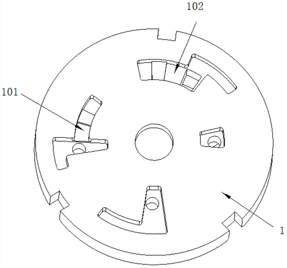
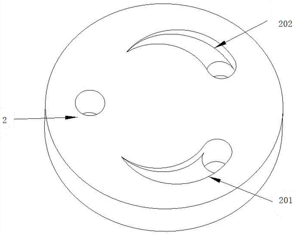
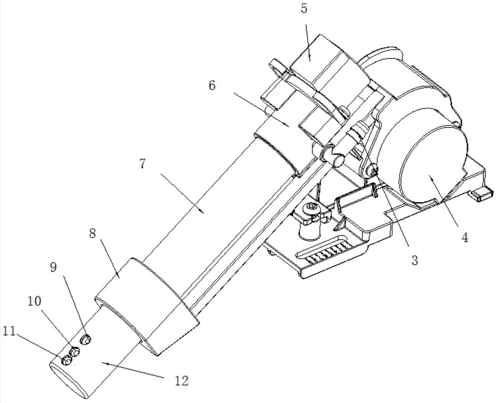
[0038] see Figure 3 to Figure 9 , is a structural schematic diagram of the present invention, including a cleaning device pipe body 7, one end of the cleaning device pipe body 7 is connected to the water circuit switching surge chamber 6, the other end is connected to the self-cleaning chamber 8, the self-cleaning chamber 8 is connected to the nozzle 12, and the water circuit switching surge chamber 6 is connected to the pressure regulating motor 5, and the waterway switching pressure regulating chamber 6 is also provided with a water inlet 3, and the waterway switching pressure regulating chamber 6 is connected with the pipe body moving motor 4. A waterway switching val...


PUM


Abstract

The invention relates to an intelligent toilet bowl cleaning device which comprises a cleaning device pipe. One end of the cleaning device pipe is connected with a water channel switching pressure regulating chamber, and the other end thereof is connected with a self-cleaning chamber. The self-cleaning chamber is connected with a nozzle. The water channel switching pressure regulating chamber is connected with a pressure regulating motor and provided with a water inlet. The pressure regulating motor is connected with a pipe moving motor. A water channel switching valve plate and a water channel switching core are disposed in the water channel switching pressure regulating chamber. The water channel switching valve plate is mounted on the water channel switching core and can rotate around the same. The intelligent toilet bowl cleaning device has the advantages that functions of water channel switching, cleaning water air mixing, cleaning function pressure regulation and hip washing and massaging can be achieved without an external water channel switching device, an air pump and a direct-current water pump; compared with a traditional product, the device is water saving, comfortable to use, simple to mount and use, simple in pipe arrangement and low in cost.

Description

technical field [0001] The invention relates to a cleaning device, in particular to an intelligent toilet cleaning device. Background technique [0002] The traditional intelligent toilet cleaning device is mainly an external water switching device for the cleaning device according to the water switching method, and different cleaning functions of the cleaning device are realized by adjusting the external water switching device. Its working process is water source→decompression device→waterway switching device→cleaning device. The waterway switching device of this solution takes up a lot of space, and the pipeline arrangement is complicated. [0003] There are two main types of traditional smart toilet cleaning devices according to the pressure adjustment method: [0004] (1) The cleaning device is equipped with a miniature DC water pump, and the cleaning water pressure can be adjusted by adjusting the working voltage of the water pump; its working process is water source→...

Claims


Application Information

Patent Timeline
Patent Type & Authority Applications(China)
IPC IPC(8): E03D9/08
Inventor 彭坤夏漪婷
Owner 无锡欧枫科技有限公司
Why Eureka
Try Eureka