Control mechanism for rapid deflection reflection mirror with rotation center arranged at reflection surface and method thereof

A technology of rotation center and control mechanism, applied in the direction of optical components, optics, instruments, etc., can solve the problems of optical system error, small displacement output range, small deflection range, etc., achieve high rigidity, reduce optical system error, and large deflection range Effect

Active Publication Date: 2015-08-19
XI AN JIAOTONG UNIV
View PDF3 Cites 18 Cited by
  • Summary
  • Abstract
  • Description
  • Claims
  • Application Information

AI Technical Summary

Problems solved by technology

Piezoelectric materials have the characteristics of high displacement output precision, small size, and low energy consumption. However, due to the small displacement output range, the current two-dimensional fast deflection mirror control mechanism of piezoelectric materials generally has the disadvantage of too small deflection range. Moreover, there is often a distance between the center of rotation of the mirror and the upper surface (reflection surface) of the mirror, which will cause errors in the optical system

Method used


Image

  • Control mechanism for rapid deflection reflection mirror with rotation center arranged at reflection surface and method thereof
  • Control mechanism for rapid deflection reflection mirror with rotation center arranged at reflection surface and method thereof
  • Control mechanism for rapid deflection reflection mirror with rotation center arranged at reflection surface and method thereof

Examples


Embodiment Construction

[0018] The present invention will be described in further detail below in conjunction with the accompanying drawings and specific embodiments.

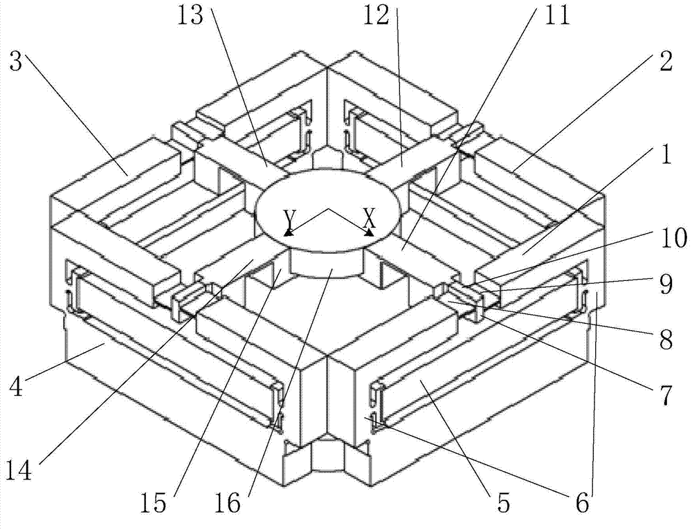
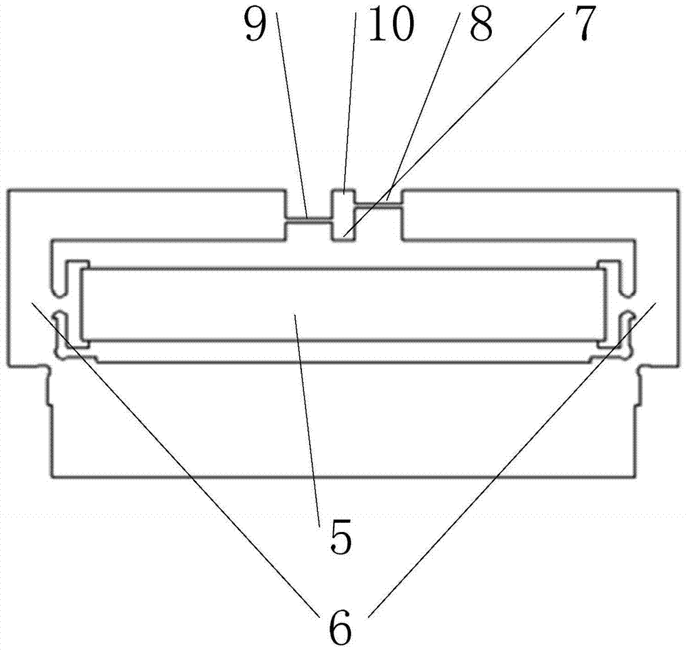
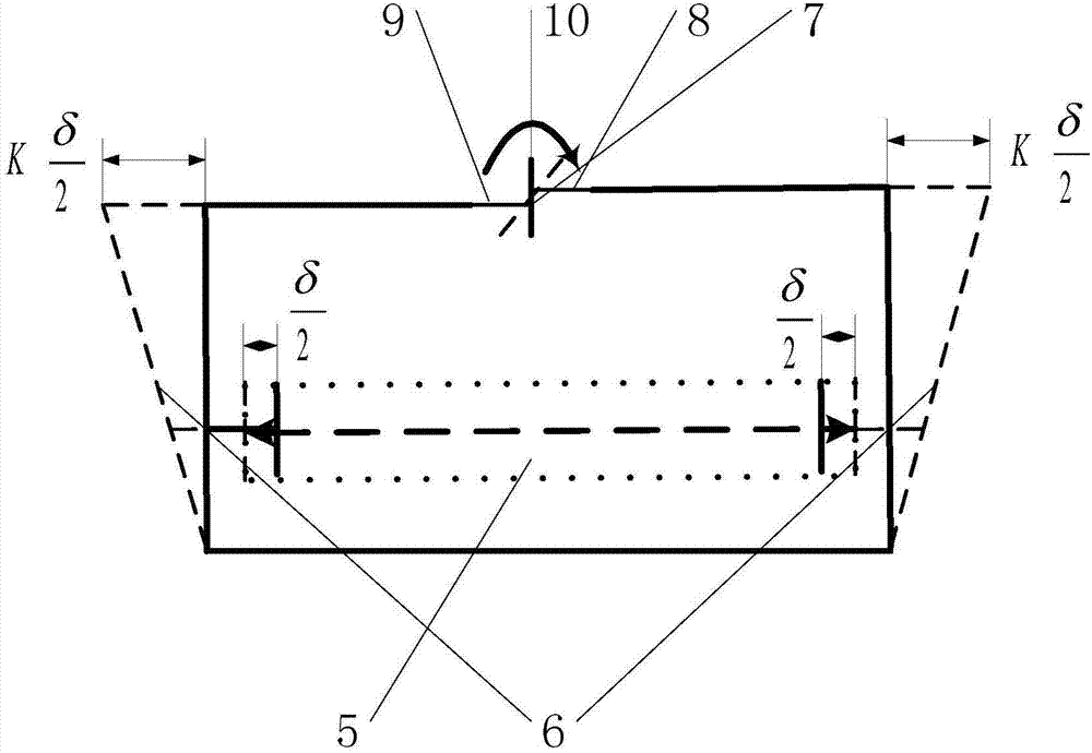
[0019] like figure 1 As shown, the control mechanism and method of the fast deflection mirror whose rotation center is on the reflection surface of the present invention includes a first drive mechanism 1 and a third drive mechanism 3 located at both ends of the X deflection axis and symmetrical with respect to the Y deflection axis, located on the Y deflection axis Two ends and the second driving mechanism 2 and the fourth driving mechanism 4 that are symmetrical about the X deflection axis, the X deflection axis and the Y deflection axis are vertical and located in the same plane; the first drive mechanism 1 includes the long axis and the X deflection axis A rod-type displacement amplifying mechanism 6 with a vertical rotating shaft, a piezoelectric driver 5 arranged in the long axis of the rod-type displacement amplifying mechanism...


PUM


Abstract

The invention provides a control mechanism for a rapid deflection reflection mirror with the rotation center arranged at the reflection surface and a method thereof. The control mechanism comprises a first driving mechanism and a third driving mechanism which are arranged at the two ends of an X-axis of deflection and symmetrical about a Y-axis of deflection, and a second driving mechanism and a fourth driving mechanism which are arranged at the two ends of the Y-axis of deflection and symmetrical about the X-axis of deflection. The first driving mechanism is connected with a mirror supporting structure via a first flexible hinge perpendicular to the first driving mechanism. The structure and the size of the second driving mechanism, the third driving mechanism and the fourth driving mechanism are identical to those of the first driving mechanism, and the second driving mechanism, the third driving mechanism and the fourth driving mechanism are connected with the mirror supporting structure via a second flexible hinge, a third flexible hinge and a fourth flexible hinge respectively. The side surface of the reflection mirror is fixed on the mirror supporting structure. The mirror surface of the reflection mirror and the X-axis of deflection and the Y-axis of deflection are arranged in the same plane. The invention also provides a control method of the control mechanism. The control mechanism has relatively large deflection range and also has the characteristics of high response speed, small size and low weight.

Description

technical field [0001] The invention belongs to the technical field of light beam control, and in particular relates to a control mechanism and method for a fast deflecting mirror whose rotation center is located on a reflecting surface. Background technique [0002] In recent years, with the rapid development of microelectronics technology, bioengineering, aerospace engineering and other disciplines, two-dimensional fast deflecting mirrors have become increasingly important and widely used in astronomical telescopes, image stabilization, compound axis precision tracking, and aiming optical systems. In the above application system, in order to obtain good compensation, tracking and control effects, it is required that the fast deflection control mechanism of the beam must have high angular deflection sensitivity and fast response capability. Piezoelectric materials have the characteristics of high displacement output precision, small size, and low energy consumption. However...

Claims


Application Information

Patent Timeline
Patent Type & Authority Applications(China)
IPC IPC(8): G02B26/08
Inventor 敬子建徐明龙朱建阳田征
Owner XI AN JIAOTONG UNIV
Why Eureka
Try Eureka