Calculation method of ultimate load of compression-bending members

A calculation method and ultimate load technology, applied in the field of numerical calculation, can solve problems such as long program running time, tediousness, and many iterative cycles

Active Publication Date: 2018-03-09
CHINA ELECTRIC POWER RES INST +3
View PDF4 Cites 0 Cited by
  • Summary
  • Abstract
  • Description
  • Claims
  • Application Information

AI Technical Summary

Problems solved by technology

[0011] However, first, when the program of the existing calculation method is running, the corresponding curvature needs to be obtained by calling the M-P-Ф relationship program for each point of the component in all iteration cycles, so the calculation amount is large and the convergence time is long; second, Since the rotation angle θ needs to be calculated separately in the recursion process i , thus increasing the amount of data storage; third, because in the interpolation process, the bending moment and curvature of the section at the midpoint of the element need to be used as the average value of the element bending moment and curvature, so it is comparable to directly calculating the bending moment and curvature at the endpoint is more cumbersome than that; fourth, for a given load P, it is necessary to give an appropriate rotation angle θ 0 , otherwise the convergence speed of the iterative cycle is slow; fifth, due to the large number of iterative cycles, if the number of component units needs to be increased to improve the calculation accuracy, the amount of calculation will increase significantly
Therefore, the recursive algorithm process of the existing calculation method of the ultimate load of the bending member is complicated, iterative cycles are many, the amount of data processing is large, and the convergence is poor. The application of the model in engineering is greatly limited

Method used


Image

  • Calculation method of ultimate load of compression-bending members
  • Calculation method of ultimate load of compression-bending members
  • Calculation method of ultimate load of compression-bending members

Examples


Embodiment Construction

[0063] Embodiments of the present invention will now be described with reference to the drawings, in which like reference numerals represent like elements.

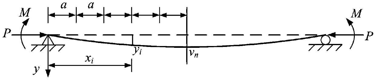
[0064] Such as figure 2 Shown is a schematic diagram of a press-bending member hinged at both ends, in which the axial pressure P and the bending moment M act symmetrically, and the member is divided into n unit segments equidistant along the axis direction, and the length of each segment is a, then the end points of each unit coordinates are x i , the point deflection is y i (i=0, . . . , n).

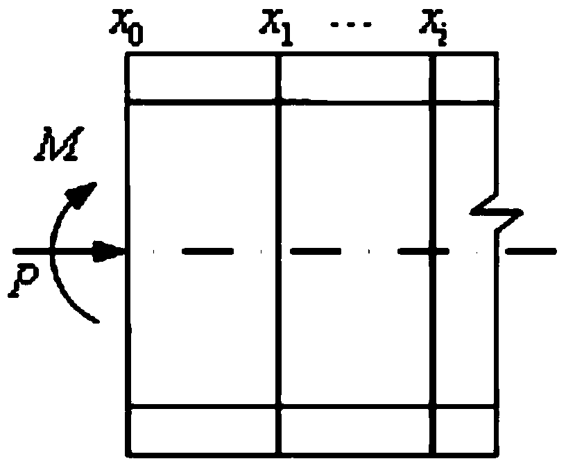
[0065] Such as Figure 3(a)-3(c) Shown is a schematic diagram of the calculation and analysis of the wide-flange I-shaped cross-section compression-bending member subjected to compression bending. Among them, Figure 3(a) is the end side view of the component; as shown in Figure 3(b), the coordinate point x i The section at is divided into many units, the superscript i indicates the axial position of the section, the subscrip...


PUM


Abstract

The invention provide a computing method for an extreme load of a compression-bending member, which comprises the following steps: (1) dividing the compression-bending member into n units; (2) constructing a bent deflection function of the compression-bending member; (3) computing the deflection and curvature of each unit endpoint of the compression-bending member; (4) computing bending moment and axial pressure on a section; (5) establishing a nonlinear balance equation set; (6) computing load of the compression-bending member; (7) computing an iteration initial vector and an iteration initial matrix; (8) computing an iteration vector and an iteration matrix; (9) judging whether iteration is ended according to a convergence condition I; (10) judging whether the iteration is ended according to a convergence condition II. The method is simple in a computing process, small in data capacity, high in computing efficiency and fast in speed.

Description

technical field [0001] The invention relates to a numerical calculation method in structural design, in particular to a calculation method for the ultimate load of a compression-bending component. Background technique [0002] Many existing structural design calculations are based on linear elastic structures, that is, the structures are limited to work within the elastic range. When the maximum stress of the structure reaches the ultimate stress σ of the material n , the structure will be destroyed, so the strength condition is: [0003] σ max ≤[σ]=σ n / K [0004] In the formula, σ max is the maximum working stress of the structure; [σ] is the allowable stress of the material; σ n is the ultimate stress of the material, and for brittle materials it is the strength limit σ b , for plastic materials its yield limit σ s ; K is the safety factor. Structural analysis based on this assumption is called elastic analysis. [0005] From the perspective of structural streng...

Claims


Application Information

Patent Timeline
Patent Type & Authority Patents(China)
IPC IPC(8): G06F17/12
Inventor 秦剑夏拥军万建成陈宏学孙烨舒东跃张坤义张松华
Owner CHINA ELECTRIC POWER RES INST
Why Eureka
Try Eureka