A brush installation structure and a brush installation method

An installation structure and brush technology, applied in circuits, current collectors, electrical components, etc., can solve problems such as the inability to guarantee positive pressure, the influence of the use of electric rotary connectors, and the inability to guarantee the contact angle between the brush and the electric slip ring, etc. Improve quality and service life, ensure the effect of rotating torque

Inactive Publication Date: 2018-01-16
CHINA AVIATION OPTICAL-ELECTRICAL TECH CO LTD
View PDF5 Cites 0 Cited by
  • Summary
  • Abstract
  • Description
  • Claims
  • Application Information

AI Technical Summary

Problems solved by technology

The Chinese utility model patent with the authorized announcement number CN20171177U and the authorized announcement date of 2011.03.30 discloses an electric rotary connector that is convenient for maintenance. This electric rotary connector includes a connector body on which an axial interval is fixed. The supporting device is provided, and the two supporting devices are connected by an axially extending bridging beam, that is, a bracket connector. The middle position of the two bracket connectors is provided with a slip ring assembly, that is, a slip ring bushing and an electric slip ring arranged on it, to support The device is rotatably assembled on the slip ring assembly, wherein the bracket connector is a plate-shaped structure with an axially extending square hole. The bracket connector is connected with a brush bracket, and the left and right brushes are welded on the brush bracket. A flaring structure with a gradually larger diameter is formed in the up and down direction. The brush on the brush bracket passes through the square hole on the bracket connector and is tangent to the electric slip ring to achieve sliding contact with the electric slip ring. Considering the entire connection Due to the volume of the connector, the width of the square hole on the bracket connector is narrow and smaller than the maximum opening angle of the left and right brushes. When installing the brush bracket on the connector body through the bracket connector, the maximum opening angle of the two brushes needs to be adjusted. When the angular positions are squeezed toward each other and the distance between the angular positions of the two brushes is smaller than the width of the square hole, the brush can pass through the square hole on the bracket connector, so that the brush will be squeezed due to extrusion. Due to certain deformation, the contact angle between the brush and the slip ring after assembly cannot be guaranteed, the positive contact pressure cannot be guaranteed, and the friction between the brush and the slip ring cannot be accurately calculated when the slip ring rotates. The total rotational torque cannot be guaranteed, which has a great impact on the use of the electric rotary connector and reduces the service life of the electric rotary connector

Method used


Image

  • A brush installation structure and a brush installation method
  • A brush installation structure and a brush installation method
  • A brush installation structure and a brush installation method

Examples


Embodiment 1

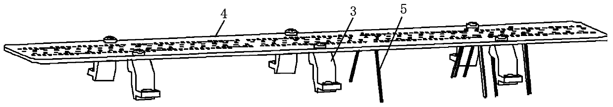
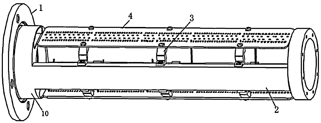
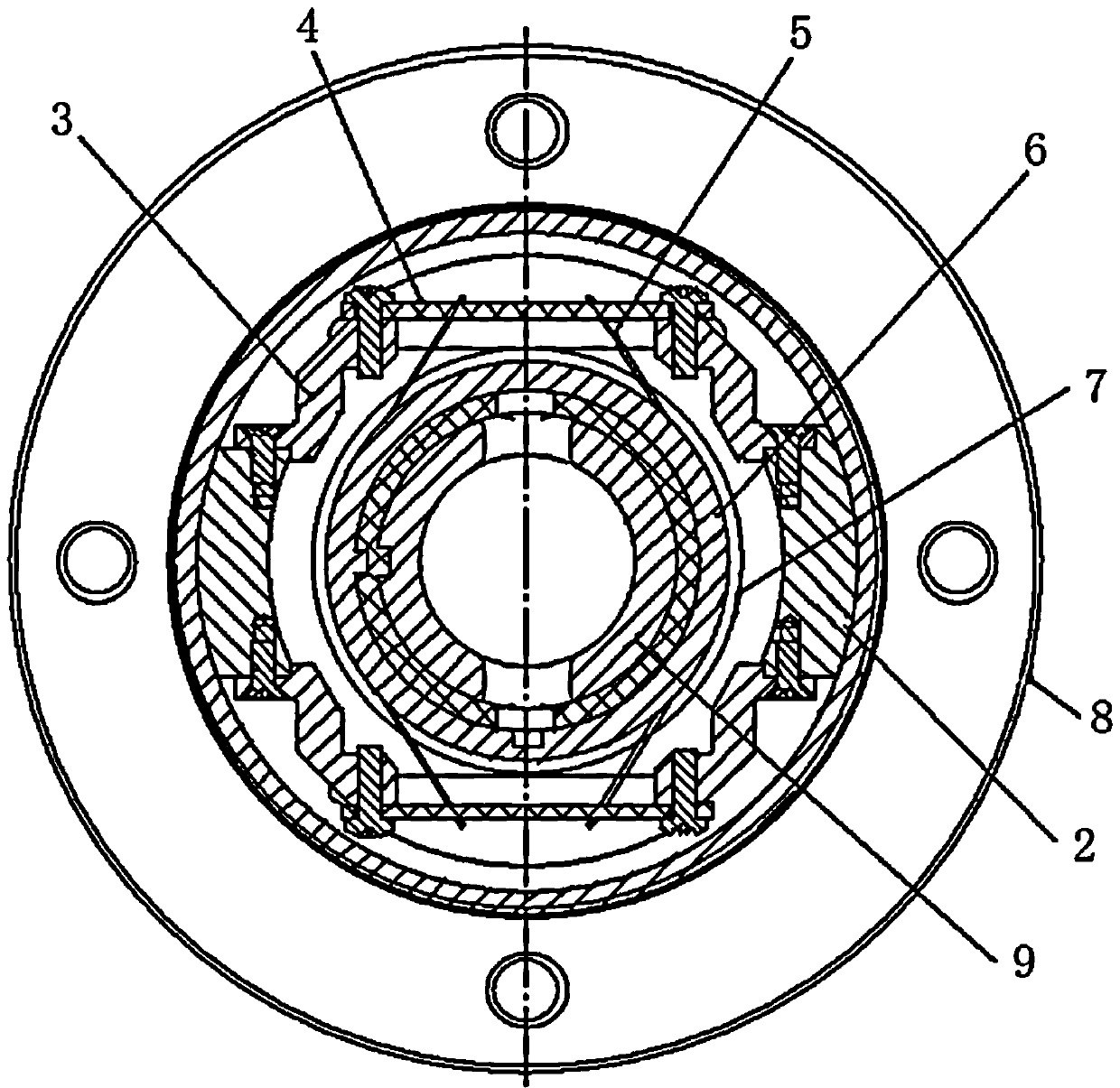
[0024] Embodiment 1 of the brush installation method of the present invention includes the following steps: the first step is to assemble the left connector of the bracket connector on the brush bracket from left to right from the left side of the left brush, and install the bracket connector The right connecting piece, which is separate from the left connecting piece, is assembled on the brush holder from the right side of the right brush from right to left; the second step is to connect the left and right connecting pieces to the connector body respectively.

[0025] Embodiment 2 of the brush installation method of the present invention: the difference from Embodiment 1 is that in the first step, the left connector of the bracket connector is assembled on the brush bracket from bottom to top from the upper side of the left brush.

[0026]Embodiment 3 of the brush installation method of the present invention: the difference from Embodiment 1 is that in the first step, the righ...


PUM


Abstract

The invention provides a brush mounting structure and a brush mounting method. The brush mounting structure comprises a brush holder and a holder connector. The brush holder is equipped with left and right brushes. The left and right brushes jointly form a flaring structure of which the diameter increases gradually in the up-down direction. The holder connector comprises a left connector and a right connector which are arranged in a split way in the left-right direction, wherein the left connector is assembled on the brush holder from left to right from the left side of the left brush or assembled on the brush holder from bottom to top from the upper side of the left brush, and the right connector is assembled on the brush holder from right to left from the right side of the right brush or assembled on the brush holder from bottom to top from the upper side of the right brush. The left connector and the right connector are respectively equipped with a fixed mounting structure used for being fixedly connected with the connector body. Thus, the left and right brushes arranged on the brush holder do not need to be extruded, the left and right brushes are not deformed in the mounting process, many problems and defects caused by brush deformation in the prior art are not caused, and the quality and service life of an electrical rotary connector are improved.

Description

technical field [0001] The invention relates to a brush installation structure and a brush installation method. Background technique [0002] With the rapid development of electric power and communication equipment, the application of electrical connectors is becoming more and more extensive. The electrical rotary connector plays a very important role as a connector that can realize rotary conductive connection. The Chinese utility model patent with the authorized announcement number CN20171177U and the authorized announcement date of 2011.03.30 discloses an electric rotary connector that is convenient for maintenance. This electric rotary connector includes a connector body on which an axial interval is fixed. The supporting device is provided, and the two supporting devices are connected by an axially extending bridging beam, that is, a bracket connector. The middle position of the two bracket connectors is provided with a slip ring assembly, that is, a slip ring bushing ...

Claims


Application Information

Patent Timeline
Patent Type & Authority Patents(China)
IPC IPC(8): H01R39/02H01R39/39H01R43/12
Inventor 王唱媛朱晓东
Owner CHINA AVIATION OPTICAL-ELECTRICAL TECH CO LTD
Why Eureka
Try Eureka