Visibility estimation device, visibility estimation method, and safe driving support system

A visual recognition, road marking technology, applied in the field of visual recognition estimation device, visual recognition estimation and safe driving support system, can solve the problems of excessive information notification, decreased driver's attention, driver's boredom, etc. The effect of the amount of information

Inactive Publication Date: 2015-08-19
MITSUBISHI ELECTRIC CORP
View PDF11 Cites 7 Cited by
  • Summary
  • Abstract
  • Description
  • Claims
  • Application Information

AI Technical Summary

Problems solved by technology

[0003] However, when introducing these various safe driving support technologies, it is necessary to pay attention to the reduction of the driver's attention due to excessive information notification to the driver
For example, when driving on the street, there will be many pedestrians and road signs, so notifying all of these will make the driver feel annoying, and the information that should be actively notified may not be delivered correctly questions for drivers

Method used


Image

  • Visibility estimation device, visibility estimation method, and safe driving support system
  • Visibility estimation device, visibility estimation method, and safe driving support system
  • Visibility estimation device, visibility estimation method, and safe driving support system

Examples


Embodiment approach 1

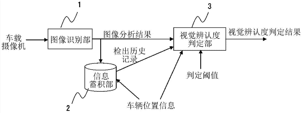
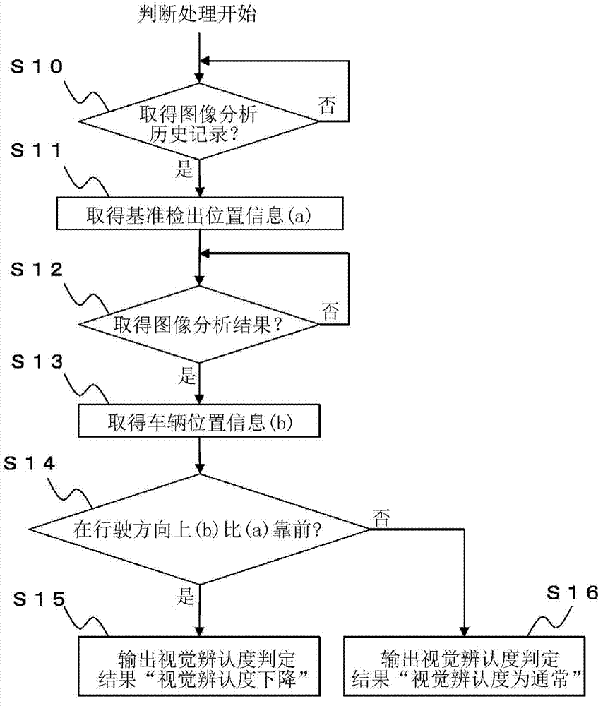
[0034] figure 1 It is a diagram showing the visibility estimation device according to Embodiment 1 of the present invention. As the visibility estimating device, in addition to the device that estimates the visibility of the driver driving the vehicle, there is also a device that estimates the visibility of pedestrians, but in the first embodiment, the estimated driver's visibility A visibility estimating device for visibility will be described. The same applies to the following embodiments. As shown in the figure, the visibility estimation device according to Embodiment 1 is composed of an image recognition unit 1 , an information storage unit 2 , and a visibility determination unit 3 . in addition, figure 2 The flow of the visibility determination by the visibility determination unit 3 is shown.

[0035] The image recognition unit 1 is installed in the vehicle, takes the image captured by the vehicle-mounted camera ahead in the driving direction as input, and outputs th...

Embodiment approach 2

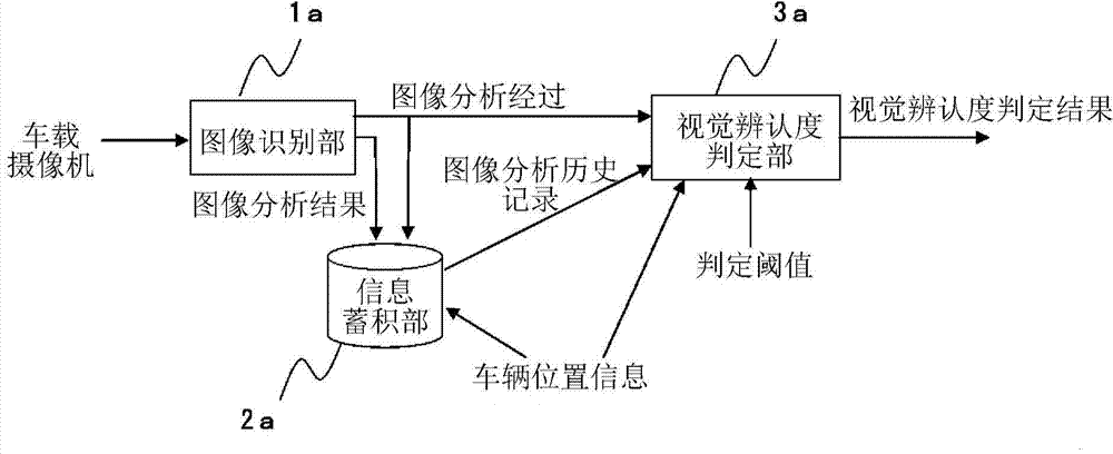
[0047] image 3 It is a diagram showing a driver's visibility estimation device according to Embodiment 2 of the present invention. and figure 1 The difference is that the image analysis process is output from the image recognition unit 1a to the visibility determination unit 3a instead of the image analysis result, and the image analysis process is accumulated in the information storage unit 2a. That is, in Embodiment 1, when the image recognition unit 1 can completely detect the traffic sign or the like to be recognized, it outputs the type and description content, while the image recognition unit 1a of the second embodiment can output the traffic sign etc. In the case of information, the image analysis process is also output at the time of passing a predetermined point. The other aspects are the same, so the explanation is omitted. Figure 4 The flow of the visibility determination by the visibility determination unit 3a is shown.

[0048] use image 3 and Figure 4 A...

Embodiment approach 3

[0057] In Embodiment 1, visibility estimation is performed using changes in detection positions of road markings, and in Embodiment 2, visibility estimation is performed using changes in image analysis levels of road markings. On the other hand, in this embodiment, visibility estimation is performed using the change of the distance (detection distance) from the detection position of a road mark to a road mark.

[0058] Figure 5 It is a diagram showing the driver's visibility estimating device according to the third embodiment. and figure 1 The difference is that there is a road marking position recording unit 21 and a detection distance recording unit 22 in the information storage unit 2b, and a plurality of information and figure 1 different data. The other aspects are the same, so the explanation is omitted.

[0059] Positional information of road markings such as traffic signs and / or traffic lights is recorded in the road marking position recording unit 21 in the informa...


PUM


Abstract

In order to estimate changes in ambient visibility, this visibility estimation device is provided with: an image recognition unit (1) that detects landmarks by analyzing images; an information storage unit that records, as past detection history, image analysis results for the landmarks detected by the image recognition unit (1), and the detection positions when the image recognition unit (1) detects the landmarks; and a visibility determination unit (3) that estimates a change in visibility on the basis of comparisons between past detection positions recorded in the information storage unit (2) and the detection positions when the image recognition unit (1) redetects landmarks corresponding to the detection history recorded in the information storage unit (2).

Description

technical field [0001] The present invention relates to a technique for performing control so that the notification does not become excessive and hinder driving and / or walking when notifying various information to drivers and / or pedestrians. Background technique [0002] In recent years, various safe driving support technologies aimed at improving the safety of motor vehicle driving have been developed. For example, there is a system that displays an alarm on a display device prepared in the car and / or emits an alarm sound through a speaker when approaching a vehicle in front or a vehicle around it, and there is also a system that notifies pedestrians and / or signs on the shoulder of the road. There is a system to prevent the driver from overlooking. [0003] However, when introducing these various safe driving support technologies, it is necessary to pay attention to the reduction of the driver's attention due to excessive notification of information to the driver. For exa...

Claims


Application Information

Patent Timeline
Patent Type & Authority Applications(China)
IPC IPC(8): G08G1/16G01C21/26
CPCG06K9/00805G08G1/166G01C21/3602G01C21/3629G01C21/3655G08G1/167G06V20/58G06V20/56G06F18/24G06F18/22B60K35/00B60Q9/00
Inventor 村山修羽藤淳平
Owner MITSUBISHI ELECTRIC CORP
Why Eureka
Try Eureka