Rotary turning blade

A technology of turning and inserts, which is applied in the field of indexable turning inserts, can solve the problems of scratches, affecting the surface quality of workpieces, and cannot be applied at the same time, so as to achieve the effect of good surface quality

Active Publication Date: 2015-08-26
ZHUZHOU CEMENTED CARBIDE CUTTING TOOLS CO LTD
View PDF8 Cites 2 Cited by
  • Summary
  • Abstract
  • Description
  • Claims
  • Application Information

AI Technical Summary

Problems solved by technology

[0002] In the process of metal turning, the same insert is usually not suitable for semi-finishing and finishing at the same time, that is, when it is used for semi-finishing, the chip control is good, but when it is used for finishing, the chips are not controllable. Specifically, the same Turning inserts have good cutting comprehensive performance in semi-finishing, but in finishing, especially in small depth of cut and small feed, the chips are difficult to break and control, and then wrap around the workpiece, tool, and fixture. As the process continues, the accumulated chips will inevitably scratch the processed surface, thereby affecting the surface quality of the workpiece, and even extruding on the tip of the tool or hitting the blade to cause abnormal failure of the blade, especially when processing soft materials, stainless steel and other plastic and The above phenomenon is more serious when using materials with better viscosity
Therefore, the versatility of turning inserts has always been a major problem in metal turning.
[0005] Chinese patent document CN103008697A discloses a turning insert, by setting a small bump and a large chip breaker in the shape of a cam that is closely connected to the small bump in the edge angle plane of the blade to meet the requirements of different cutting depths and feed conditions. Chip control, but this structural design still has some shortcomings in processing the outer circle and end face processing to guide the chip

Method used


Image

  • Rotary turning blade
  • Rotary turning blade
  • Rotary turning blade

Examples


Embodiment Construction

[0026] The present invention will be further described in detail below in conjunction with the accompanying drawings and specific embodiments.

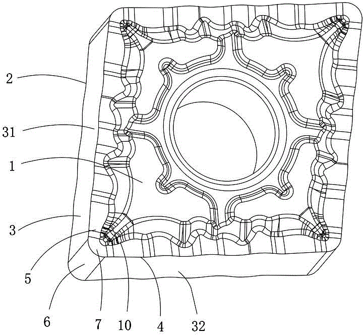
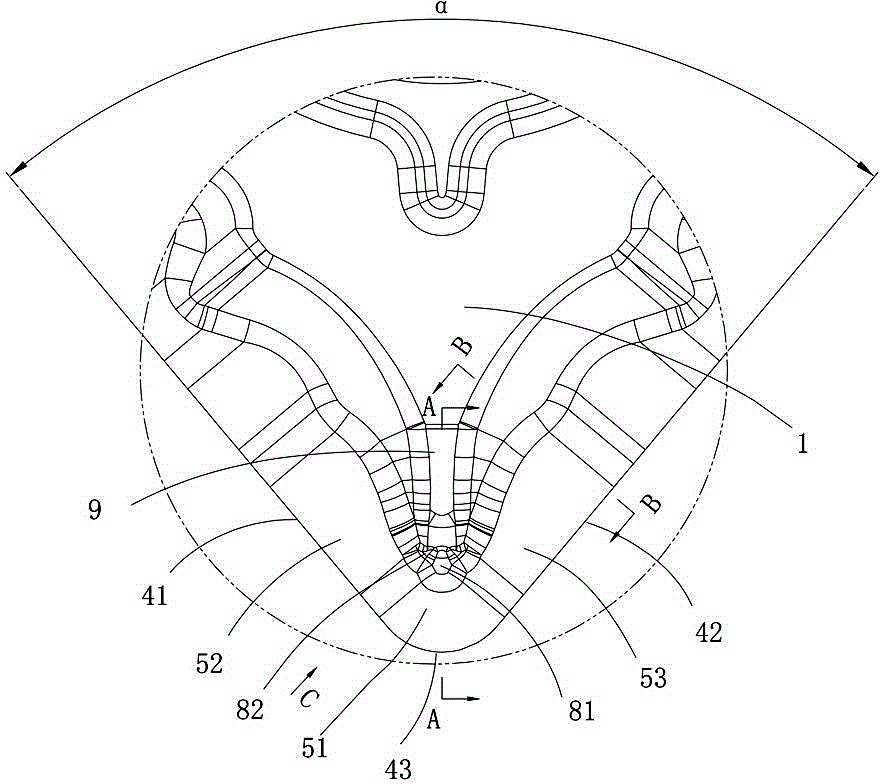
[0027] Figure 1 to Figure 6 An embodiment of the indexable turning insert of the present invention is shown, the indexable turning insert comprises an upper surface 1, a lower surface 2 and a plurality of side walls 3 connecting the upper surface 1, the lower surface 2, the upper surface 1 in The guiding surface formed by the cutting edge 4 is the rake face 5, and the two adjacent side walls 31, 32 are connected and transitioned by the cylindrical surface 6. The upper surface 1, the side walls 31, 32 and the cylindrical surface 6 intersect to form a tool tip 7, adjacent to each other. The included angle between the two side walls 31, 32 is the tool tip angle α, the cutting edge 4 includes a tool tip edge 43 and two side edges 41, 42, and the cutting edge 4 is symmetrical to the geometric bisector of the tool tip included angle α dis...


PUM


Abstract

The invention discloses a rotary turning blade; the upper surface of the blade at a guiding surface formed on a cutting edge is a front blade surface; two adjacent sidewalls transit through the connection of a cylindrical surface; the upper surface, the sidewalls and the cylindrical surface intersect to form the point of a knife; the front blade surface corresponding to a blade tip edge and two side edges are divided into the front blade surface of the blade tip edge and the front blade surfaces of two side edges; the front blade surfaces of two side edges transit toward the front blade surface of the blade tip edge, and the included angle between the front blade surfaces of two side edges and the front blade surface of the blade tip edge grows big gradually, and the width of the edges grows small gradually; a chip breaker groove is set at the center of the top of the blade tip; the chip breaker groove comprises an oval large protruding ball, two oval small protruding balls and a T-shaped boss; the oval large protruding ball and the two oval small protruding balls distribute in a radiation way; the boss is set at one side of the oval small protruding balls far from the blade tip; and the bottom of the chip breaker groove transits in a smooth way. The blade has the blade tip and has the advantages of sharpness and intensity, controllable chip flow and shape. The blade is suitable for fine finishing and semi-finishing etc.

Description

technical field [0001] The invention relates to the field of metal cutting, in particular to an indexable turning insert. Background technique [0002] In the process of metal turning, the same insert is usually not suitable for semi-finishing and finishing at the same time, that is, when it is used for semi-finishing, the chip control is good, but when it is used for finishing, the chips are not controllable. Specifically, the same Turning inserts have good cutting comprehensive performance in semi-finishing, but in finishing, especially in small depth of cut and small feed, the chips are difficult to break and control, and then wrap around the workpiece, tool, and fixture. As the process continues, the accumulated chips will inevitably scratch the processed surface, thereby affecting the surface quality of the workpiece, and even extruding on the tip of the tool or hitting the blade to cause abnormal failure of the blade, especially when processing soft materials, stainles...

Claims


Application Information

Patent Timeline
Patent Type & Authority Applications(China)
IPC IPC(8): B23B27/22
CPCB23B27/143B23B2200/081B23B2200/321
Inventor 王许超徐唯刘志林崔宝宝刘敏
Owner ZHUZHOU CEMENTED CARBIDE CUTTING TOOLS CO LTD
Why Eureka
Try Eureka