Grinding machine for fine conical surface of air valve

A valve and cone surface technology, which is applied in the direction of grinding machines, grinding bed, grinding machine parts, etc., can solve the problems of difficulty in guaranteeing grinding quality, increasing manufacturing costs, adhesion, etc., to ensure positioning accuracy and reduce contact The effect of area and good positioning

Pending Publication Date: 2021-06-11
江苏吉斯特科技有限公司
View PDF0 Cites 2 Cited by
  • Summary
  • Abstract
  • Description
  • Claims
  • Application Information

AI Technical Summary

Problems solved by technology

During the grinding process of the valve cone surface, the valve is clamped in the workpiece spindle, and the grinding wheel used to grind the valve is installed on the rotating grinding wheel shaft. The high-speed rotating grinding wheel shaft must be dynamically balanced to ensure its operation. The stability of the process, due to factors such as wear during the use of the grinding wheel, it is difficult to maintain the balance accuracy of the grinding wheel shaft, and the stability of its operation will be difficult to guarantee, which brings instability to the grinding quality of the valve precision cone surface grinder In order to ensure the grinding quality, it is necessary to perform dynamic balancing operations on the grinding wheel shaft assembly, which will affect the working efficiency of the grinding machine on the one hand, and on the other hand, it is difficult to accurately grasp when the dynamic balancing operation is required; for those who use the electric spindle As far as the grinding wheel shaft is concerned, the stability and reliability of the grinding wheel motorized spindle installation is also a factor that affects the grinding quality. Usually the grinding wheel motorized spindle is installed on the grinding wheel motorized spindle mounting seat, and its installation accuracy is determined by the grinding wheel motorized spindle casing and the grinding wheel motor The matching accuracy of the motorized spindle mounting hole on the spindle mounting seat is guaranteed. There will always be a fit gap between the grinding wheel motorized spindle casing and the motorized spindle mounting hole. Such a gap will make the grinding wheel motorized spindle in an unstable position. For high For precision valve grinders, this is also one of the factors that affect the running accuracy of the grinding wheel shaft
[0003] The precise dressing of the grinding wheel is the premise to ensure the grinding quality. The dressing process of the grinding wheel is carried out through the relative movement between the grinding wheel dresser and the grinding wheel. The dressing disc is installed on the dressing electric spindle, and the grinding work surface of the rotating grinding wheel is trimmed by using the rotating grinding wheel dressing disc; usually, the dressing process of the grinding wheel and the dressing quality of the grinding wheel are determined by manual observation, which requires operation The personnel have certain experience, which makes the dressing quality of the grinding wheel unable to be guaranteed, which is unacceptable for high-precision valve grinders; in addition, the dressing electric spindle used to drive the grinding wheel dressing disc is installed on the On the spindle mounting seat, the installation accuracy is guaranteed by the matching accuracy between the trimming motorized spindle casing and the motorized spindle mounting hole on the trimming motorized spindle mounting seat, there will always be a fit gap between the trimming motorized spindle housing and the motorized spindle mounting hole , such a gap will make the dressing electric spindle in an unstable position state, which is also one of the factors that affect the quality of grinding wheel dressing and then the grinding quality for high-precision valve grinders
[0004] During the grinding process of the valve cone surface, the grinding force of the grinding wheel on the valve will form component forces along the radial and axial directions of the valve, and the radial component force will cause the valve to bend and deform during the grinding process. , and its axial component force will cause the valve to have a tendency to run out of the large end face during the grinding process, which will have a great impact on the grinding quality, and to eliminate this impact, by reducing the grinding process It is a feasible solution to reduce the grinding force by increasing the amount of grinding, but this will greatly reduce the production efficiency of the grinding process
[0005] During the grinding process, grinding will produce a large amount of grinding debris. If it cannot be cleaned in time, the grinding debris will adhere to the grinding surface of the grinding wheel, which will reduce the grinding efficiency and increase the temperature of the grinding area. Ordinary grinding The process uses the grinding fluid to take away the wear debris and cool down the grinding area. However, for the valves made of nickel-based superalloy materials, serious adhesion will occur during the grinding process of nickel-based superalloys. Grinding is extremely difficult, which makes it difficult to guarantee the grinding quality, and the wear of the grinding wheel is serious, and the temperature in the grinding area is also higher. Once the grinding fluid is not supplied in time, there may even be a possibility of fire
[0006] In addition, when the workpiece spindle clamps the valve before grinding, the clamping position of the valve must be accurately positioned to ensure the position and dimension accuracy of the valve cone surface after machining. The large end face of the valve is a commonly used positioning reference in valve processing surface, but the surface shape and position accuracy of the big end of the valve are not high. Using this surface as the positioning reference plane may often cause positioning errors and affect the position and dimension accuracy of the valve grinding process. If the end surface of the large end of the valve is improved in the previous process Manufacturing accuracy, although the positioning requirements during valve grinding can be guaranteed, but this will inevitably increase the manufacturing cost

Method used


Image

  • Grinding machine for fine conical surface of air valve
  • Grinding machine for fine conical surface of air valve
  • Grinding machine for fine conical surface of air valve

Examples


Embodiment Construction

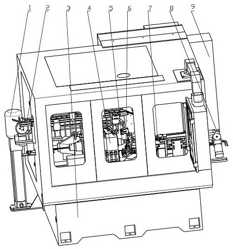
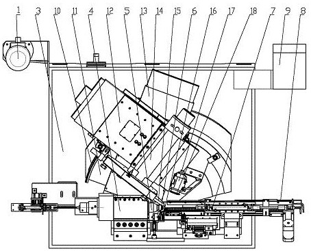
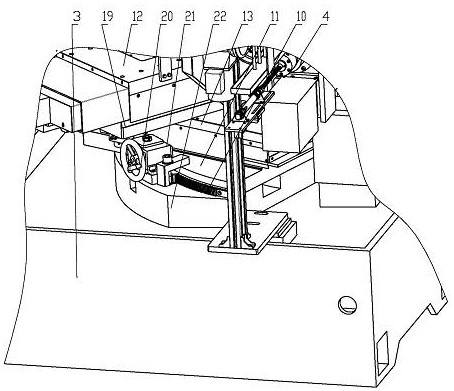
[0055] exist figure 1 and figure 2 In the shown valve precision cone surface grinding machine, the bed 3 is the basic support member of the grinding machine, supports and drives the workpiece spindle assembly 4 for clamping the workpiece spindle 5 of the valve 16 to be ground, and is used to install and drive the grinding machine. The grinding wheel shaft assembly 14 for the grinding wheel 15, the dressing shaft assembly 17 for installing and driving the grinding wheel dressing disc 18, the automatic feeding device 2, the automatic discharging device 8, the cover, the control system and other functional components are all supported on the bed 3, a grinding fluid nozzle (not shown in the figure) opposite to the valve grinding position between the valve 16 and the grinding wheel 15 is installed on the bed 3, and the grinding fluid nozzle and the grinding fluid booster pump 1 connected, the grinding fluid booster pump 1 is a general product purchased in the market, and a fire e...


PUM


Abstract

The invention discloses a grinding machine for a fine conical surface of an air valve. The grinding machine comprises a machine body, a workpiece main shaft assembly, a grinding wheel shaft assembly and a finishing shaft assembly, wherein an online dynamic balance device is arranged in the grinding wheel shaft assembly, a sound wave monitoring device is arranged in the finishing shaft assembly, and an air valve auxiliary supporting device opposite to the grinding wheel shaft assembly is arranged on one side of the workpiece main shaft assembly on the machine body; an air valve positioning device provided with a universal positioning head is arranged at the position opposite to the workpiece spindle assembly, a grinding fluid spray nozzle in communication with a grinding fluid booster pump is arranged at the position opposite to the valve grinding position, and a fire extinguishing device is arranged on the lathe bed; and the fire extinguishing device comprises a temperature inductive sensor and a fire extinguishing spray nozzle of which the mounting positions are opposite to the air valve grinding part. The grinding machine for the fine conical surface of the air valve can maintain the dynamic balance precision of the grinding wheel shaft for a long time, automatically monitors the grinding wheel dressing quality, improves the air valve positioning precision and reduces the bending deformation of the air valve in the grinding process, and is high in grinding efficiency and safe and reliable to use.

Description

technical field [0001] The invention relates to a grinding machine, in particular to a valve-specific grinding machine for high-precision grinding of conical surfaces of high-temperature material nickel-based alloy valves. Background technique [0002] The valve is an important part of the engine. With more stringent emission requirements, in order to reduce emissions and improve the thermal efficiency of the engine, the base material used in the valve is gradually replaced by nickel-based alloy base material from the original ordinary martensitic steel and austenitic steel. , Ordinary abrasives no longer have the ability to process high-temperature nickel-based alloy materials. Therefore, ceramic CBN abrasives have been developed to cope with the grinding of nickel-based alloy materials. Grinding of the valve cone surface is a key process of valve processing. During the grinding process of the valve cone surface, the valve is clamped in the workpiece spindle, and the grindi...

Claims


Application Information

Patent Timeline
Patent Type & Authority Applications(China)
IPC IPC(8): B24B5/14B24B41/02B24B41/04B24B41/06B24B47/20B24B47/22B24B49/00B24B57/02
CPCB24B5/14B24B41/02B24B41/04B24B41/06B24B47/20B24B47/22B24B49/00B24B57/02
Inventor 周红伟钟明华
Owner 江苏吉斯特科技有限公司
Why Eureka
Try Eureka