Automatic pushing platform for woodworking

An automatic and woodworking technology, which is applied in the direction of wood processing equipment, manufacturing tools, sawing components, etc., can solve the problems of technical workers with low cultural quality, incompetence in work, and inability to meet production requirements, so as to reduce work-related injuries, improve safety, The effect of high production efficiency

Inactive Publication Date: 2015-08-26
FOSHAN CITY SANSHUI DISTRICT YOUSHENG WOOD IND CO LTD
View PDF10 Cites 8 Cited by
  • Summary
  • Abstract
  • Description
  • Claims
  • Application Information

AI Technical Summary

Problems solved by technology

[0002] In wood processing plants and wood-based panel production, woodworking band saws or sliding table saws are all manually operated, which is labor-intensive and has many work-related injuries, and the technical workers generally have low cultural quality and are difficult to be competent for the job, and there are fewer and fewer qualified workers. , it is difficult to meet the needs of production

Method used


Image

  • Automatic pushing platform for woodworking
  • Automatic pushing platform for woodworking

Examples


Embodiment 1

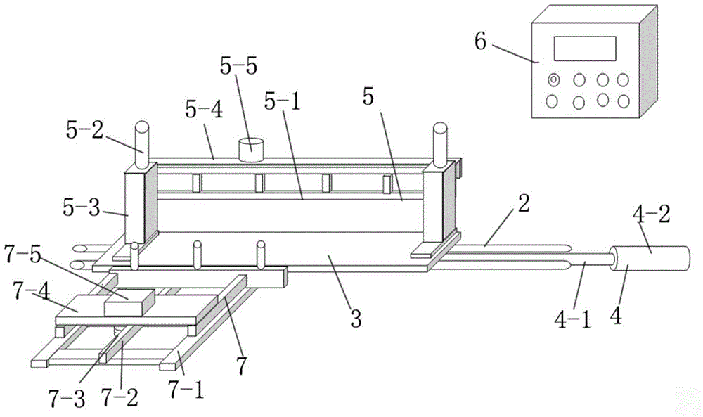
[0024] Such as figure 1 As shown, the present invention is an automatic woodworking push table which includes a frame 1, a guide rail-2 arranged on the frame 1, and a push table 3 slidingly matched with the guide rail-2, connected to drive the push table to slide along the guide rail-1 Device 4, the wood positioning mechanism 5 arranged on the push platform, and the main controller 6 connected to the control power unit and the wood positioning mechanism, the power unit 4 includes a pressure cylinder one 4-1 arranged on the frame, and a pressure cylinder one 4 The pressure rod 4-2 of -1 is connected to one end of the push platform, and the pressure rod is used as the power to replace the manual operation. Wherein, the pressure cylinder 4-1 can be in the form of an air cylinder or a hydraulic cylinder, and what this embodiment uses is an air cylinder .

[0025] The outside of push platform 3 is provided with timber cross-feeding mechanism 7, and timber cross-feed mechanism comp...

Embodiment 2

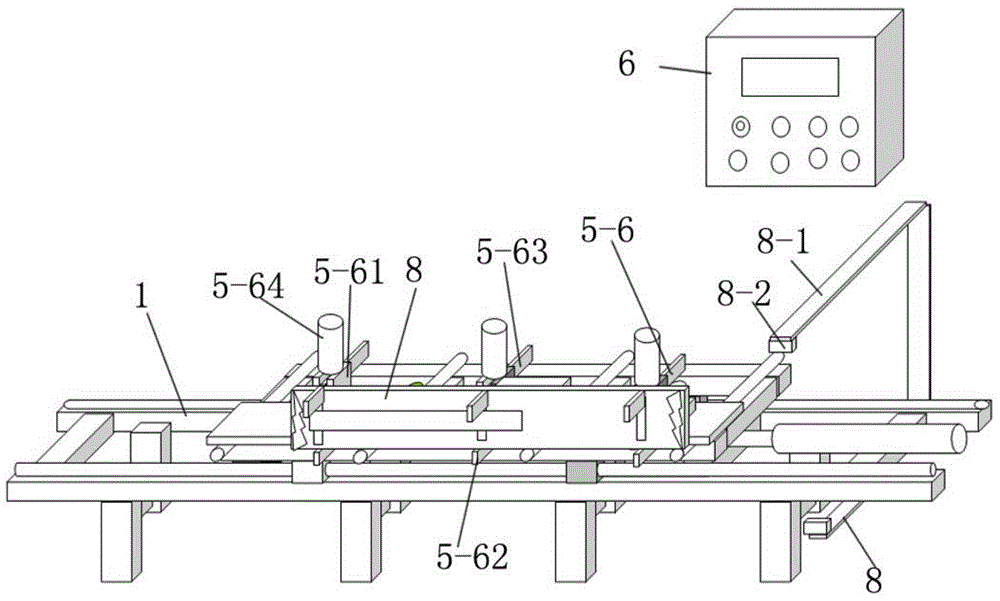
[0028] Such as figure 2 As shown, in the present embodiment, the push platform is a log push platform. One side of the log push platform is provided with a positioning baffle 8. Timber positioning mechanism 5 comprises at least three groups of manipulators 5-6 arranged along the direction of the guide rail on the log push platform. Between the fixed clip 5-62 and the movable clip 5-63 matched with the fixed clip, one or both ends of the fixed clip and the movable clip extend to the outside of the positioning splint on both sides, and the movable clip is connected with a drive The lifting pressure cylinder 3 5-64 forms a clamping structure corresponding to logs.

[0029] An infrared positioning device 8 for identifying the diameter of the log is arranged outside the log pushing platform, and the signal output end of the infrared positioning device is connected to the main controller 6 . The infrared positioning device 8 includes a C-shaped bracket 8-1 perpendicular to the g...


PUM


Abstract

The invention discloses an automatic pushing platform for woodworking. The automatic pushing platform for woodworking is characterized by comprising a rack, first guide rails arranged on the rack, a pushing platform body matched with the first guide rails in a sliding mode, a power device which is connected with the pushing platform body and drives the pushing platform body to slide along the first guide rails, a wood positioning mechanism arranged on the pushing platform body, and a master controller which is connected with the power device and the wood positioning mechanism and used for controlling the power device and the wood positioning mechanism. The power device comprises a first pressure cylinder arranged on the rack, and a pressure rod of the first pressure cylinder is connected to one end of the pushing platform body. Manpower can be saved by half compared with the prior art; production efficiency is high; the possibility of occupational injuries is reduced, and safety performance is greatly improved.

Description

technical field [0001] The invention relates to the technical field of woodworking machinery, and more specifically relates to a wood pushing platform capable of automatic feeding and cutting. Background technique [0002] In wood processing factories and wood-based panel production, woodworking band saws or sliding table saws are all manually operated, which is labor-intensive and has many work-related injuries. Moreover, skilled workers generally have low cultural quality and are difficult to do their jobs, and there are fewer and fewer qualified workers. , it is difficult to meet the needs of production. Contents of the invention [0003] The object of the present invention is to provide a woodworking automatic sliding platform with simple structure, high production efficiency, reduced possibility of work-related injuries and high safety in order to solve the deficiencies of the prior art. [0004] The present invention uses the following technical solutions to achieve...

Claims


Application Information

Patent Timeline
Patent Type & Authority Applications(China)
IPC IPC(8): B27B29/00B27B29/02B27B25/00
CPCB27B29/00B27B25/00B27B29/02
Inventor 扶明松丁世德
Owner FOSHAN CITY SANSHUI DISTRICT YOUSHENG WOOD IND CO LTD
Why Eureka
Try Eureka