An automatic identification device

A marking device and driving device technology, applied in printing, stamping, etc., can solve problems such as easy movement of the stamping mechanism, hard impact of the circuit board, damage to the stamped object, etc., to achieve reliable guidance, simple structure, and freedom from wear effect

Inactive Publication Date: 2017-08-08
JOINT STARS TECH
View PDF1 Cites 0 Cited by
  • Summary
  • Abstract
  • Description
  • Claims
  • Application Information

AI Technical Summary

Problems solved by technology

[0004] For this reason, the technical problem to be solved by the present invention is that if the clamp clamps the stamp mechanism too tightly, it is easy to cause hard impact on the stamped object such as paper, circuit board, etc., thereby causing damage to the stamped object. Too loose, the stamping mechanism is easy to move back and forth in the fixture, resulting in unclear stamping

Method used


Image

  • An automatic identification device
  • An automatic identification device

Examples


Embodiment 1

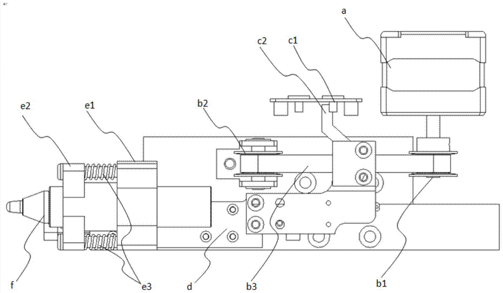
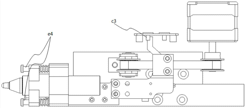
[0030] like Figure 1-2 As shown, a kind of automatic marking device of the present embodiment includes: a marking mechanism with a marking member f; a driving device that drives the marking mechanism to move back and forth; the marking mechanism also includes a The fixed seat e1 can move back and forth in a straight line and is arranged on the movable seat e2 on the fixed seat e1, the identification part f is installed on the movable seat e2, and the fixed seat e1 and the movable seat e2 A biasing component is installed between them, and the biasing force of the biasing component acts on the movable seat e2, so that the movable seat e2 has a tendency to move along the marking direction. In this embodiment, the identification part f is a seal, and the identification mechanism is a seal mechanism. Of course, in other embodiments, the identification part f can also be an oil-based pen, etc., which can be marked on paper or circuit boards. other structures. In the following, th...


PUM


Abstract

The invention discloses an automatic marking device, which comprises: a marking mechanism with a marking part (f); a driving device that drives the marking mechanism to move back and forth; the marking mechanism also includes a A fixed seat (e1), a movable seat (e2) arranged on the fixed seat (e1) that can move back and forth in a straight line, the identification member (f) is installed on the movable seat (e2), and the A biasing part is installed between the fixed seat (e1) and the movable seat (e2), and the biasing force of the biasing part acts on the movable seat (e2), so that the movable seat (e2) has an edge To identify the trend of direction movement. The automatic marking device of the present invention can buffer the impact of the stamp on the object to be stamped when stamping, thereby avoiding the problem that the stamp mechanism directly hits the object to be stamped hard and causes damage to the object to be stamped and the seal, so that the stamp is free from Wear and tear, the quality of stamping can also be maintained for a long time.

Description

technical field [0001] The invention relates to an identification device, in particular to an automatic identification device. Background technique [0002] The automatic stamping machines in the prior art generally realize automatic stamping by the joint action of a stamp mechanism, a drive mechanism, a control mechanism or a detection mechanism to reduce manpower. However, in the actual operation process, the automatic stamping mechanism will be easily worn and the stamping will not be clear, which will eventually affect the appearance of the stamping, and even affect the effect of the stamping. [0003] Such as the prior art Chinese invention patent CN101875267A "an automatic stamp machine" is the above-mentioned technology. It controls the downward rotation of the ink pad through the photoelectric switch to detect the signal of the paper in place, and the second iron core is turned to the left so that the first iron core drives the connecting rod downward to move the se...

Claims


Application Information

Patent Timeline
Patent Type & Authority Patents(China)
IPC IPC(8): B41K3/04B41K3/66
Inventor 黄韬
Owner JOINT STARS TECH
Why Eureka
Try Eureka