Self-enclosed packer

A self-sealing and packer technology, which is applied to floating buildings and other directions, can solve the problems of packer damage and failure, and achieve the effects of steel saving, simple installation process and high safety factor

Active Publication Date: 2015-08-26
SINO RUBBER TECH CO LTD
View PDF9 Cites 4 Cited by
  • Summary
  • Abstract
  • Description
  • Claims
  • Application Information

AI Technical Summary

Problems solved by technology

The main disadvantages are: the application of water depth is limited (especially the mechanical packer); the pile 18 falls rapidly, which may cause damage and failure of the packer

Method used


Image

  • Self-enclosed packer
  • Self-enclosed packer
  • Self-enclosed packer

Examples


Embodiment 1

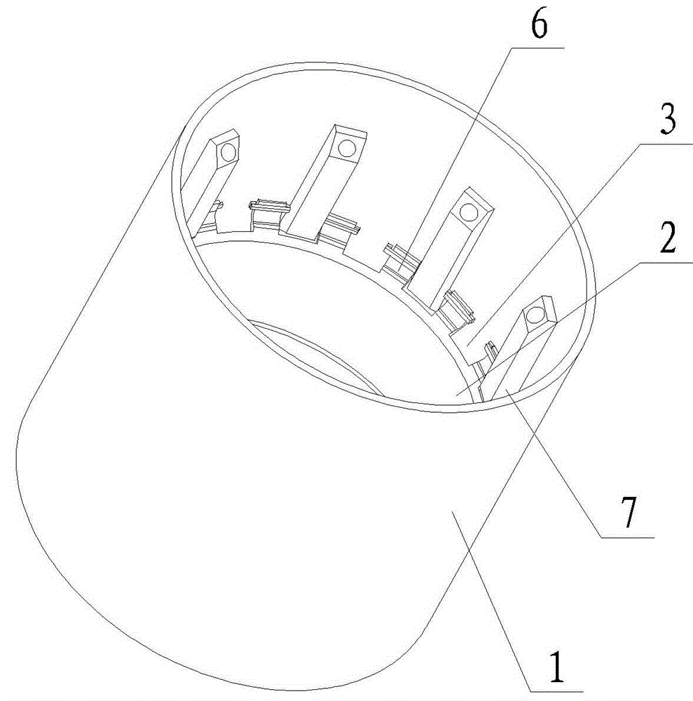
[0024] Embodiment one: see attached figure 1 , a self-sealing packer, located between the sleeve 1 and the pile 18, its key lies in: it includes a rubber sleeve 2 coaxial with the sleeve 1 and arranged at the inner bottom of the sleeve 2, and the bottom of the rubber sleeve 2 is fixed by a bottom fixing device It is sealingly connected with the sleeve 1 and forms a grout accommodating cavity with the gap between the rubber sleeve 2 and the sleeve 1 , and the top is connected with the sleeve 1 by means of a top fixing device and is provided with a grouting port 3 .

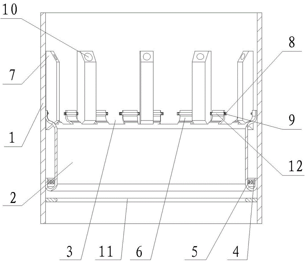
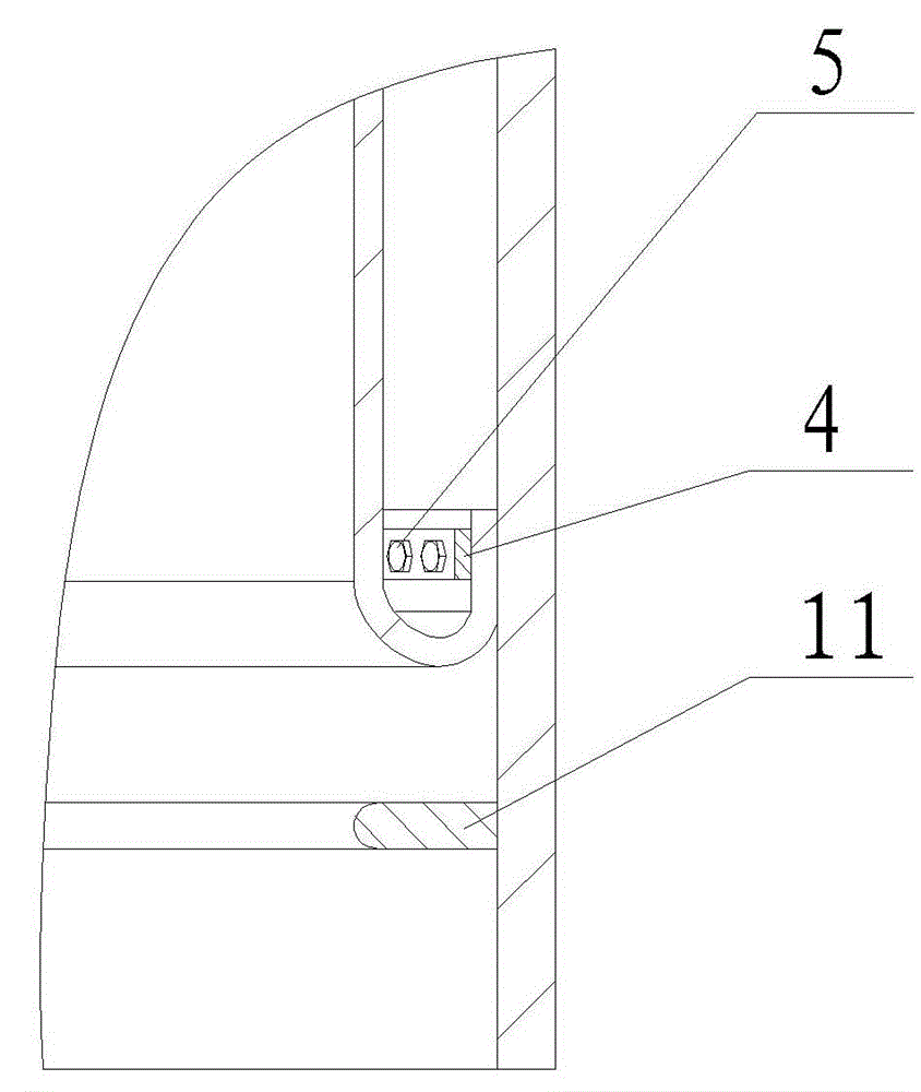
[0025] See attached figure 2 with image 3 , the bottom of the rubber sleeve 2 is bent towards the sleeve 1, and the bent part forms a sealed and fixed structure with the sleeve 1 by means of a bottom fixing device. The bent portion of the rubber sleeve 2 forms a gap between the rubber sleeve 2 and the sleeve 1 , thereby forming a cement slurry accommodating cavity.

[0026] The inner diameter of the middle s...


PUM


Abstract

The invention discloses a self-enclosed packer which is applied to sealing of a ring-shaped gap between a pile and a sleeve in a marine drilling platform, and arranged between the sleeve and the pile, The self-enclosed packer is characterized by comprises a rubber sleeve; the rubber sleeve is coaxial with the sleeve and arranged at the inner bottom of the sleeve; the bottom of the rubber sleeve is in sealed connection with the sleeve through a bottom fixing device; a cement mortar accommodating cavity is formed in a gap between the rubber sleeve and the sleeve; the top of the rubber case is connected with the sleeve through a top fixing device; mortar grouting openings are formed in the top of the rubber case. Only the rubber case and the corresponding fixing devices are subjected to automatic sealing, so that the self-enclosed packer is simple in structure, easy to manufacture and low in cost; besides, the self-enclosed packer has the advantages of being high in safe factor like an active packer, simple to mount like a passive packer, free of pipelines and power systems, and the like.

Description

technical field [0001] The invention belongs to the technical field of packers for offshore fixed platforms, in particular to a self-sealing packer. Background technique [0002] See attached Figure 8 , The offshore fixed platform is generally composed of an upper module 15 and a lower jacket 17 . The fixing of the jacket 17 and the seabed 19 is generally accomplished through a fixed connection between the sleeve 1 placed at the bottom of the main leg of the jacket 17 and the steel pile 18 passing through the sleeve 1 and driven into the seabed 19 . The fixing between the inner diameter of the sleeve 1 and the outer diameter of the pile 18 is achieved by means of cement grouting. [0003] The main function of the offshore underwater packer is to block the space between the inner side of the annular sleeve 1 and the outer diameter of the pile 18 at the bottom of the sleeve 1 when grouting after the piling is completed, so as to prevent the cement slurry from flowing out. F...

Claims


Application Information

Patent Timeline
Patent Type & Authority Applications(China)
IPC IPC(8): B63B35/44
Inventor 田建德刘保权杜宗周马美琴周建峰张军邱昌盛付华淼卢瑞钊
Owner SINO RUBBER TECH CO LTD
Why Eureka
Try Eureka