Grain bagging machine

A bagging machine and grain technology, applied in the field of machinery, can solve the problems of large fan size, long process, and grain residue, and achieve the effects of fewer parts, improved production efficiency, and simple structure

Active Publication Date: 2017-01-04
凤阳九龙粮贸有限公司
View PDF10 Cites 0 Cited by
  • Summary
  • Abstract
  • Description
  • Claims
  • Application Information

AI Technical Summary

Problems solved by technology

However, this kind of grain bagging machine needs to go through the empty suction tank, the grain outlet, and then enter the high-level granary from the grain pile to the bag. The process in the middle is long and there are many steps. The specifications of the fan used are relatively large; on the other hand, after the grain is transported through a long and tortuous pipeline, some grain will remain in the pipeline, which will make it difficult to clean the pipeline after a long time; on the other hand, the parts involved Still more, maintenance is more troublesome

Method used


Image

  • Grain bagging machine
  • Grain bagging machine
  • Grain bagging machine

Examples


Embodiment Construction

[0025] The present invention will be described in further detail below in conjunction with the accompanying drawings and specific embodiments.

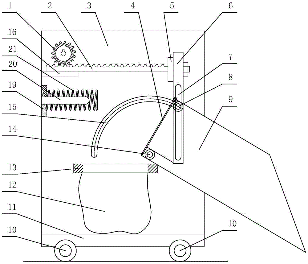
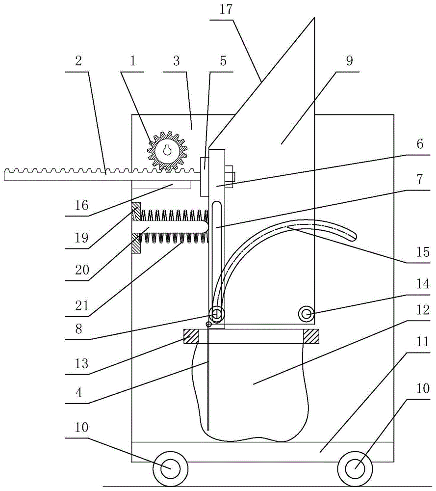
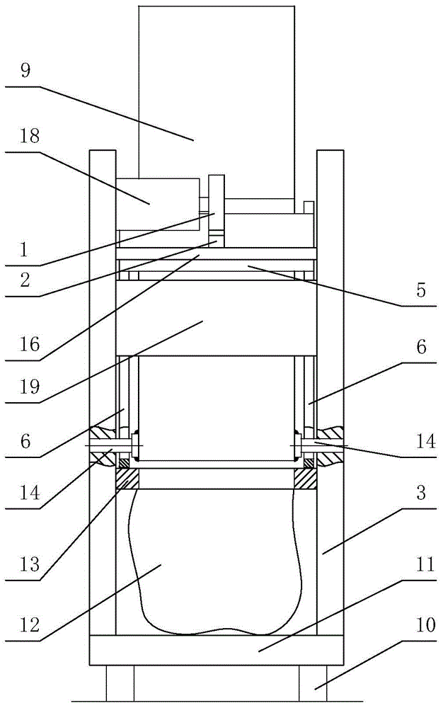
[0026] Depend on Figure 1 ~ Figure 3 As can be seen from the schematic structural diagram of the grain bagging machine of the present invention, it includes a movable base 11, a frame plate 3, a bag fixing device 13 for socketing a grain bag 12, a hopper 9, a hopper driving device and a hopper buffer device. The frame board 3 is two pieces, and the lower end of each frame board 3 is fixedly connected to the edge of the movable base 11 . The bag fixing device 13 is connected between the two rack plates 3 and is located in the middle of the rack plates 3 in the vertical direction. The hopper 9 is rotatably connected to the two frame plates 3 , and the rotatable connection point is located above the edge of the bag fixing device 13 . The hopper driving device includes a motor 18, a gear 1, a rack 2, a rack support plate 16, two verti...


PUM


Abstract

The invention discloses a grain bagging machine. A rack is arranged horizontally and is connected with a rack supporting board in a sliding mode. The two ends of the rack supporting board are connected with the inner sides of two rack boards respectively. One end of the rack is connected with the center of a sliding rod connection board. The two ends of the sliding rod connection board are connected with the upper ends of two vertical sliding rods respectively. The lower ends of the vertical sliding rods are hinged to a hopper and are in sliding connection with the hopper along hopper tracks on the rack boards. One end of a hopper buffering device is connected to the two rack boards and located below the rack supporting board. The hopper buffering device is horizontally arranged. The free end of the hopper buffering device abuts against the hopper when the hopper turns over to the final position. By the adoption of the structure, as the grain bagging machine is small and exquisite in size, the grain bagging machine is suitable for small granaries. Meanwhile, a buffering limiting device is arranged on the rack boards, so that turnover of the hopper is buffered and limited, normal conduction of production is much ensured, and production efficiency is improved.

Description

technical field [0001] The invention relates to the technical field of machinery, in particular to a grain bagging machine. Background technique [0002] Every summer and autumn are the time periods for farmers and grain storage units to store grain intensively. Therefore, the grain needs to be bagged in the granary for better storage of grain in the later period. In the prior art, most of the granary staff bagged the grain manually. On the one hand, the labor efficiency was low, and on the other hand, multiple staff members were required to work together. Therefore, this traditional grain bagging was time-consuming. strenuous. [0003] Therefore, mechanical bagging devices appear on the market to improve production efficiency. For example, the patent number "ZL201210230214.9" disclosed on the website of the State Intellectual Property Office is the invention patent of "automatic grain collection and bagging machine", which includes a grain leak cleaning device, an auger, ...

Claims


Application Information

Patent Timeline
Patent Type & Authority Patents(China)
IPC IPC(8): B65B1/06
CPCB65B1/06
Inventor 不公告发明人
Owner 凤阳九龙粮贸有限公司
Why Eureka
Try Eureka