
Graphene surface acoustic wave filter structure and preparation method thereof

A filter structure, surface acoustic wave technology, applied in the direction of impedance network, electrical components, etc., can solve the problem of the reduction of the surface contact area between the graphene dielectric layer and the metal motor layer, increase the surface gap between the graphene dielectric layer and the metal electrode layer, Reduce the heat dissipation capacity of the SAW filter and other issues to achieve the effects of improving power tolerance, increasing stability, and reducing heat loss

Pending Publication Date: 2022-04-22
广州科慧健远医疗科技有限公司
View PDF1 Cites 2 Cited by
  • Summary
  • Abstract
  • Description
  • Claims
  • Application Information

AI Technical Summary

Problems solved by technology

[0006] However, in the above-mentioned patents, the graphene dielectric layer is directly covered on the surface of the metal electrode layer, and the actual bonding between the two is poor. Especially in a conductive and high-heat environment, the graphene dielectric layer is easy to expand, thereby increasing The gap between the graphene dielectric layer and the surface of the metal electrode layer makes the surface contact area of ​​the graphene dielectric layer and the metal motor layer smaller, thereby reducing the heat dissipation capacity of the surface acoustic filter

Method used


Image

  • Graphene surface acoustic wave filter structure and preparation method thereof
  • Graphene surface acoustic wave filter structure and preparation method thereof
  • Graphene surface acoustic wave filter structure and preparation method thereof

Examples


Embodiment Construction

[0043] The following will clearly and completely describe the technical solutions in the embodiments of the present invention with reference to the accompanying drawings in the embodiments of the present invention. Obviously, the described embodiments are only some, not all, embodiments of the present invention. Based on the embodiments of the present invention, all other embodiments obtained by persons of ordinary skill in the art without making creative efforts belong to the protection scope of the present invention.

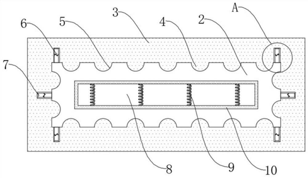
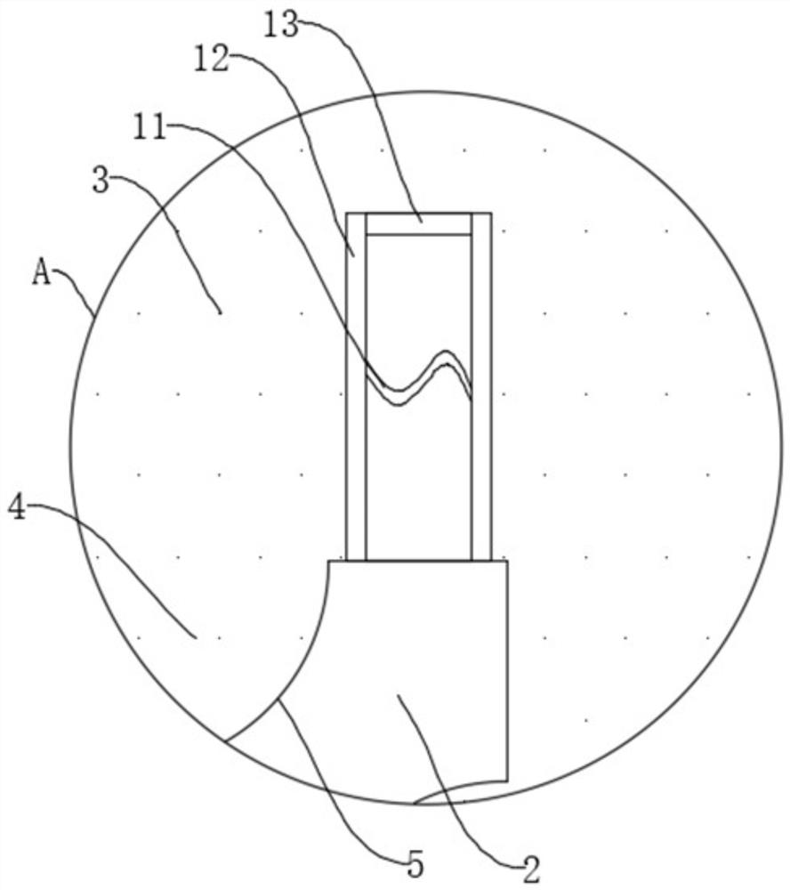
[0044] The present invention provides such Figure 1-3 A graphene surface acoustic wave filter structure shown, comprising a piezoelectric substrate 1, the top of the piezoelectric substrate 1 is fixedly provided with a metal electrode layer 2, and the outer ring of the metal electrode layer 2 is coated with a graphene layer 3. The outer ring of the metal electrode layer 2 is provided with a groove 5, and the side of the graphene layer 3 attached to the metal ...


PUM


Abstract

The invention discloses a graphene surface acoustic wave filter structure and a preparation method thereof, and relates to the field of graphene surface acoustic wave filter structures, the graphene surface acoustic wave filter structure comprises a piezoelectric substrate, a metal electrode layer is fixedly arranged above the piezoelectric substrate, a graphene layer is fixed on the outer ring of the metal electrode layer in a film coating mode, and the connection structure between the graphene layer and the metal electrode layer is firm. The graphene layer is arranged on the surface of the metal electrode layer instead of being attached to the surface of the metal electrode layer, the graphene layer is not prone to falling off due to high temperature when current passes through the metal electrode layer, and high-frequency signals are transmitted on the surface of the metal electrode layer according to the skin effect principle by means of the characteristics of high heat conductivity and high conductivity of graphene. Current is concentrated on the graphene layer on the surface layer, heat loss caused by the metal electrode layer is reduced due to the high conductivity of the graphene layer, so that insertion loss caused by resistance of the interdigital transducer is reduced, meanwhile, the heat dissipation capacity of the surface acoustic wave filter is improved due to the graphene layer with the high heat conductivity, and the effect of improving power tolerance is achieved.

Description

technical field [0001] The invention relates to the field of graphene surface acoustic wave filter structure, in particular to a graphene surface acoustic wave filter structure and a preparation method thereof. Background technique [0002] SAW filters are playing an increasingly important role in modern communication systems. Several or even dozens of SAW filters are involved in base station construction, satellite communications, and personal mobile communication equipment. With the continuous increase of the communication frequency band, the communication equipment is becoming more and more complex, and the size of the filter module is also being continuously reduced. In order to obtain large capacity and high speed at the same time, the communication filter is required to have lower insertion loss and higher power resistance. Receptivity. [0003] Research on reducing the insertion loss of surface acoustic wave filters is a hot topic in the field of surface acoustic wav...

Claims


Application Information

Patent Timeline
Patent Type & Authority Applications(China)
IPC IPC(8): H03H9/64H03H9/145H03H9/09H03H9/02H03H3/08
CPCH03H9/64H03H9/145H03H9/02834H03H9/09H03H3/08
Inventor 陈宜国
Owner 广州科慧健远医疗科技有限公司
Learn More