Clamping device and unwinding device

A clamping device and roll unwinding technology, which is applied in the direction of winding strips, transportation and packaging, thin material processing, etc., can solve the problems of inconvenient adjustment and non-adjustable clamping tension of chucks, etc., so as to save space and reduce The effect of reducing the risk of work-related injury and labor intensity

Active Publication Date: 2017-04-12
BENQ MATERIALS
View PDF6 Cites 0 Cited by
  • Summary
  • Abstract
  • Description
  • Claims
  • Application Information

AI Technical Summary

Problems solved by technology

[0004] Therefore, one of the objectives of the present invention is to provide a clamping device and a winding device to solve the problem in the prior art that the clamping tension of the chuck cannot be adjusted or is inconvenient to adjust.

Method used


Image

  • Clamping device and unwinding device
  • Clamping device and unwinding device
  • Clamping device and unwinding device

Examples


Embodiment Construction

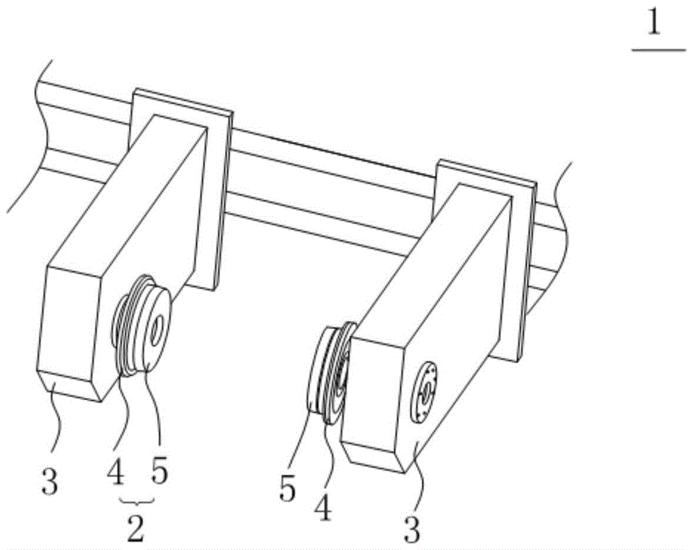
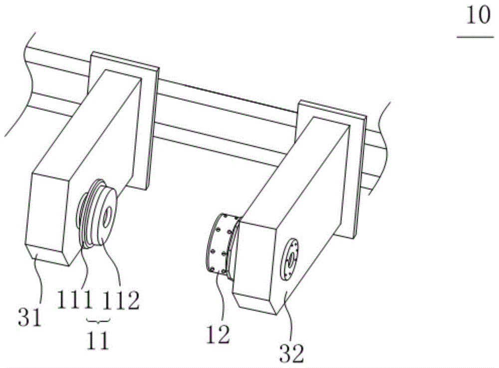
[0021] See figure 2 , figure 2 Shown is a schematic diagram of a winding and unwinding device according to the present invention. The present invention provides a winding and unwinding device 10. The winding and unwinding device 10 includes a clamping device and a core. The clamping device is used to clamp the core of the coil. The clamping device includes a first chuck 11 and a second chuck 12 oppositely arranged, and the first chuck 11 is fixed on the first bracket 31, and the second chuck 12 is fixed on the second bracket 32. The winding core is used for winding the coil, and two ends of the winding core are respectively sleeved on the first chuck 11 and the second chuck 12. The above-mentioned roll material is, for example, a film roll, and the film is, for example, a polarizing film or other optical film. When the present invention is not limited to this, for example, the above-mentioned film may also be other plastic films, such as battery film, cling film, packaging fil...


PUM


Abstract

The invention provides a clamping device and a winding and unwinding device. The clamping device comprises a first clamping head, a second clamping head, a plurality of friction plates, a friction ring, a slip ring, and an end cover, wherein the second clamping head comprises a first shaft core; the first shaft core comprises a first end part and a first shaft part; a plurality of grooves are formed in the first shaft part; each friction plate partially protrudes from a corresponding groove; the friction ring sleeves the first shaft part; the slip ring sleeves the first shaft part; the friction plates are positioned between the slip ring and the first shaft part, and in contact with the slip ring; the friction ring is positioned between the first end part and the slip ring; a plurality of raised keys are formed on the outer ring surface of the slip ring; under stress, the raised keys protrude from the outer ring surface of the slip ring to be tightly propped against a coil core; the end cover is fixed with the end, far away from the first end part, of the first shaft part in a combined manner; the friction ring and the slip ring are clamped between the first end part and the end cover. Through the adoption of the clamping device, the problem that in the prior art, the clamping tension of a clamping head is non-adjustable or is inconvenient to adjust, can be solved.

Description

Technical field [0001] The invention relates to a clamping device and a winding and unwinding device, in particular to a clamping device and a winding and unwinding device that can adjust the winding tension. Background technique [0002] In the prior art, in the roll-to-roll winding of film material, if the winding tension range of the machine needs to be extended in a large range, the slip shaft and the magnetic powder clutch are mainly used. See figure 1 , figure 1 Shown is a schematic diagram of a coil holding device in the prior art. The coil holding device 1 includes two oppositely arranged chucks 2, which are respectively fixed on two oppositely arranged brackets 3, The chuck 2 includes an end 4 and a shaft 5 connected to the end 4. The two shafts 5 are sleeved with a slip shaft, and the core of the coil is sleeved on the slip shaft, so as to realize the winding Rewinding of materials. However, the slip shaft has two disadvantages: (1) When the slip shaft is used, a whol...

Claims


Application Information

Patent Timeline
Patent Type & Authority Patents(China)
IPC IPC(8): B65H18/02B65H16/06
CPCB65H16/06B65H18/028
Inventor 孙盛军
Owner BENQ MATERIALS
Why Eureka
Try Eureka