
Inner rotor permanent magnet synchronous traction machine

A technology of synchronous traction machine and inner rotor, applied in the field of traction machine, can solve the problem of poor heat dissipation effect of stator coil package

Active Publication Date: 2015-08-26
沈阳蓝光驱动技术有限公司
View PDF16 Cites 1 Cited by
  • Summary
  • Abstract
  • Description
  • Claims
  • Application Information

AI Technical Summary

Problems solved by technology

[0005] The purpose of the present invention is to provide an inner rotor permanent magnet synchronous traction machine, which solves the problem that the existing ultra-high-speed, large-load traction machine has a poor heat dissipation effect of the stator wire package and cannot meet the requirements of manual barring of a large-torque traction machine. Needs and other technical issues, its structural design is reasonable, easy to install and unload, does not damage the main shaft, can realize high-torque manual cranking, safe and reliable in use, convenient in maintenance, significantly improves heat dissipation efficiency, and further ensures the reliability and stability of its operation ,Extended service life

Method used


Image

  • Inner rotor permanent magnet synchronous traction machine
  • Inner rotor permanent magnet synchronous traction machine
  • Inner rotor permanent magnet synchronous traction machine

Examples


Embodiment Construction

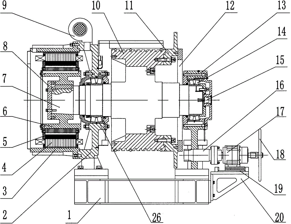
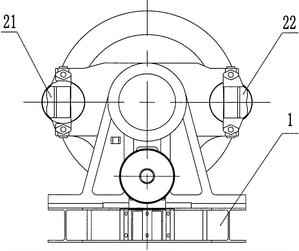
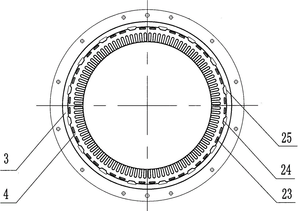
[0014] according to Figure 1~3 The specific structure of the present invention will be described in detail. The inner rotor permanent magnet synchronous traction machine is mainly designed to solve the technical problems of the existing ultra-high-speed and large-load traction machines, such as the poor heat dissipation effect of the stator wire package, and the inability to meet the needs of manual cranking of high-torque traction machines. . The original interference-connected rotor sleeve and the main shaft are set into an integrated structure, that is, the integrated main shaft is used as the rotor. It includes a frame 1, a frame 2 assembled on the frame 1 and a front support 13, a built-in stator wire package 4 assembled on the frame 2 and a casing 3 of the rotor core 5. The sub-bearings 14, 26 are assembled on the front support 13 and the main shaft 7 on the machine base 2, the traction sheave 10 and the encoder 15 assembled with the main shaft 7 are composed of the b...


PUM


Abstract

An inner rotor permanent magnet synchronous traction machine solves the technical problems that an existing ultra-high-speed and large-load traction machine stator coil is poor in cooling effect and cannot meet the manual turning requirement of a large-torque traction machine. The traction machine is technically characterized in that a rotor main shaft is connected with a rotor iron core through a rotor connecting sleeve; ventilation holes formed in the stator coil serve as a first set of cooling and ventilating duct, and a second set of cooling and ventilating duct is formed between a first ventilation groove and a second ventilation groove formed in the outer surface of the stator coil and the inner surface of a machine case; the two ventilating ducts are communicated with a centrifugal fan on the machine case; a small gear shaft of a turning gear is connected with a handwheel through a planetary speed reducer and slides in a reciprocating mode under the driving of the handwheel, and therefore the small gear shaft can be meshed with a turning gear ring or separated from the turning gear ring. The traction machine is reasonable in structural design and easy to assemble and disassemble; a main shaft cannot be damaged easily, and large-torque manual turning can be achieved; use is safe and reliable, maintenance is convenient, and cooling efficiency is remarkably improved; running reliability and running stability of the traction machine are further improved, and service life is prolonged.

Description

technical field [0001] The invention relates to an ultra-high-speed and large-load traction machine for high-rise building elevators, in particular to an inner rotor permanent magnet synchronous traction machine. It belongs to the technical field of traction machines. Background technique [0002] With the development of the city, the population of the city is increasing, and high-rise buildings are constantly appearing. More and more buildings are equipped with ultra-high speed (rated speed not less than 7.0m / s), large load (rated load not less than 1600kg) Elevators for traction machines are installed in high-rise buildings. However, due to the high power of the existing ultra-high-speed and heavy-duty traction machines, the influence of the heat dissipation effect of the stator wire package on the reliability and stability of the operation has become an extremely prominent problem. [0003] According to the problems of the existing ultra-high-speed and large-load tracti...

Claims


Application Information

Patent Timeline
IPC IPC(8): B66B11/04H02K9/06H02K7/116H02K7/102
CPCB66B11/043H02K7/102H02K7/116H02K9/06
Inventor 徐广人梁丙雪王东剑廖国华董胜波黄丽
Owner 沈阳蓝光驱动技术有限公司
Learn More