Gantry structure of portal crane

A portal-type crane and portal-seat technology, which is applied to the bottom support structure, lifting equipment braking device, load hanging components, etc., can solve the problems of inconvenient maintenance, poor stability and reliability, etc., and achieve stable structure, high reliability, The effect of large bearing capacity

Inactive Publication Date: 2015-08-26
WUXI XIEXING PORT MACHINERY
0 Cites 1 Cited by

AI-Extracted Technical Summary

Problems solved by technology

At present, the gantry of existing gantry cranes generally has the disa...

Abstract

The invention discloses a gantry structure of a portal crane. The gantry structure of the portal crane comprises a portal and a cylinder, wherein the cylinder is mounted on the portal; the portal is formed by welding a portal cross beam and a portal end beam; a plurality of cylinder reinforcing rib plates are welded in the cylinder at intervals in the height direction; a plurality of cylinder climbing ladders are arranged outside the cylinder; a cylinder protecting fence is arranged above a position, corresponding to each cylinder climbing ladder, on the cylinder; a ladder platform is arranged at the upper part of the cylinder; a platform protecting fence is arranged on the ladder platform; a portal ladder connected to the lowermost cylinder climbing ladder is arranged on the portal. The gantry structure of the portal crane has the advantages of stable structure, high reliability, large carrying force and convenience in daily maintenance and repair.

Application Domain

Base supporting structuresBraking devices for hoisting equipments

Technology Topic

Bearing capacityWaste management

Image

  • Gantry structure of portal crane
  • Gantry structure of portal crane

Examples

  • Experimental program(1)

Example Embodiment

[0016] The technical solutions of the present invention will be further described below in conjunction with the accompanying drawings and through specific implementation methods.
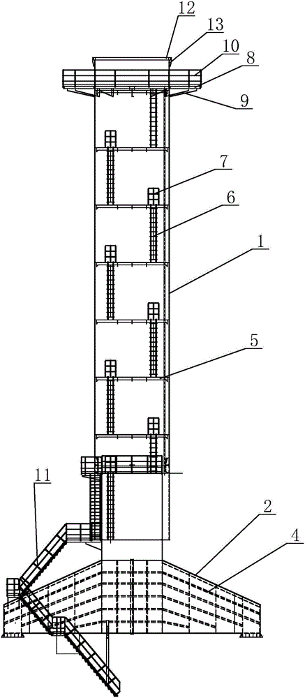
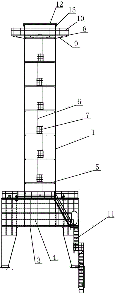
[0017] see figure 1 and figure 2 As shown, in this embodiment, a door frame structure of a portal type crane includes a door seat and a cylinder body 1, the door seat is welded by a door seat beam 2 and a door seat end beam 3, and the cylinder body 1 is fixed on the door seat beam 2, and several door seat reinforcing rib plates 4 are welded and fixed inside the door seat beam 2 and the door seat end beam 3. Inside the cylindrical body 1 are welded several pieces of cylindrical reinforcement ribs 5 at intervals along the height direction, and several cylindrical climbing ladders 6 are arranged outside the cylindrical body 1, and the several cylindrical climbing ladders 6 are staggered and fixed. Outside the cylinder 1, a connecting platform is provided between two adjacent cylinder climbing ladders 6 . And corresponding to each cylinder crawling ladder on the described cylinder 1, a cylinder guardrail 7 is arranged above it.
[0018] A ladder platform 8 is arranged on the upper part of the cylindrical body 1 , and several ladder platform reinforcing ribs 9 are welded between the bottom of the ladder platform 8 and the cylindrical body 1 . And the ladder platform 8 is provided with a platform guardrail 10, and the door seat is provided with a door seat ladder 11 connected to the cylinder crawling ladder 6 at the bottom.
[0019] A connecting flange 12 is welded on the upper end of the cylindrical body 1 , and several flange ribs 13 are welded between the bottom of the connecting flange 12 and the cylindrical body 1 .
[0020] The above embodiments have only set forth the basic principles and characteristics of the present invention, the present invention is not limited by the above-mentioned examples, and on the premise of not departing from the spirit and scope of the present invention, the present invention also has various changes and changes, and these changes and changes all fall within the scope of the claimed invention. The protection scope of the present invention is defined by the appended claims and their equivalents.

PUM

no PUM

Description & Claims & Application Information

We can also present the details of the Description, Claims and Application information to help users get a comprehensive understanding of the technical details of the patent, such as background art, summary of invention, brief description of drawings, description of embodiments, and other original content. On the other hand, users can also determine the specific scope of protection of the technology through the list of claims; as well as understand the changes in the life cycle of the technology with the presentation of the patent timeline. Login to view more.

Similar technology patents

Anticoagulation coating material and preparation method thereof

InactiveCN103721300Ahigh anticoagulant activitystable structure
Owner:HUAZHONG UNIV OF SCI & TECH

High temperature-resistant and high-insulation sealing glass and preparation method thereof

ActiveCN105776868AImprove glass fluiditystable structure
Owner:XIAN SEAL ELECTRONICS MATERIAL TECH CO LTD

Mechanical arm for plate installing

Owner:阜阳市润泰通用机械有限公司

Classification and recommendation of technical efficacy words

  • stable structure
  • Improve reliability

Silicon/carbon composite microsphere negative electrode material as well as preparation method and application for same

ActiveCN103311522Astable structureImprove charge and discharge cycle life
Owner:INST OF PROCESS ENG CHINESE ACAD OF SCI

Preparation method of magnetic graphene based oil absorption foam material

Owner:XINJIANG TECHN INST OF PHYSICS & CHEM CHINESE ACAD OF SCI

Multiple branch predictions

ActiveUS20050268075A1improve reliabilityfacilitate availability
Owner:ORACLE INT CORP

Implantable lead

ActiveUS20100137928A1good flexibility , fatigue resistance and flex lifeimprove reliability
Owner:WL GORE & ASSOC INC
Why Eureka
Try Eureka