Visible light positioning system and method based on two image sensors

An image sensor and positioning system technology, applied in positioning, radio wave measurement systems, instruments, etc., can solve problems such as difficulty in achieving accuracy, difficulty in maintaining and measuring the angle of the image sensor, and difficulty in implementing the AOA method, achieving high accuracy and great practicality. effect of value

Inactive Publication Date: 2015-08-26
WUHAN POST & TELECOMM RES INST CO LTD
View PDF4 Cites 16 Cited by
  • Summary
  • Abstract
  • Description
  • Claims
  • Application Information

AI Technical Summary

Problems solved by technology

However, in the AOA system, the accuracy of the positioning of the receiving end depends on the angle of the image sensor in the receiving end, and it is difficult to maintain and measure the angle of the image sensor. It is necessary to use a 6-axis sensor to dynamically measure the angle of the image sensor, so the AOA method is implemented Difficult, and still difficult to achieve the required precision

Method used


Image

  • Visible light positioning system and method based on two image sensors
  • Visible light positioning system and method based on two image sensors
  • Visible light positioning system and method based on two image sensors

Examples


Embodiment Construction

[0029] The present invention will be described in further detail below in conjunction with the accompanying drawings and embodiments.

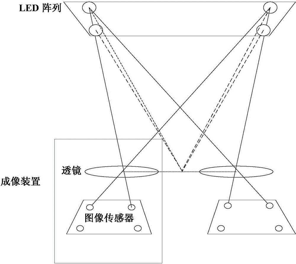
[0030] Such as figure 1 As shown, the visible light positioning system based on dual image sensors of the present invention includes a sending end and a receiving end.

[0031] The transmitting end includes an information modulating circuit and at least three LEDs arranged horizontally on the same plane. Among them, LEDs are used as light sources, and are arranged horizontally on the ceiling (in this embodiment, LED lamps). The intervals between adjacent LEDs are uniform and the positions are known, forming an LED array, and the LED light is projected vertically downward to cover the lighting area. The information modulation circuit is used to modulate the information to be sent to the light emitted by the LED, including the identification and position information of the LED, which are coded and modulated and loaded onto the light emitted by ...


PUM


Abstract

A visible light positioning system and method based on two image sensors relates to the field of LED positioning application. The visible light positioning system comprises a sending terminal and a receiving terminal, wherein the sending terminal is used for sending synthetic light signals and comprises at least three LEDs horizontally arranged on a same plane, and the receiving terminal comprises two sets of imaging devices, each of which comprises a set of lenses and an image sensor. The two image sensors are positioned on a same horizontal surface. The main shaft of each set of the lenses is perpendicular to the plane of one image sensor, and intersects with plane of the image sensors at the center of the image sensors. The two image sensors can observe at least three same LEDs. and the image device determines the projection position of LEDs on the sensors, parses the self identifier and position information sent by the optical signals of the sending terminal, and obtains the three-dimensional coordinate of the receiving terminal according to the projection geometric relation and triangular geometric principles. The application process is simple, and the positioning precision is high.

Description

technical field [0001] The invention relates to the application field of LED positioning, in particular to a visible light positioning system and method based on dual image sensors. Background technique [0002] LED (Lighting Emitting Diode, light-emitting diode) is called the fourth-generation lighting source or green light source, can be widely used in various fields, and will become the next-generation lighting technology. Because of the advantages of energy saving, safety, and wide available spectrum, LEDs can also be used in wireless optical communication systems while providing indoor lighting, and at the same time meet indoor Internet access and a series of extended applications. LED-based indoor positioning is one of the application directions with great potential. With each LED as a reference, the position and distance of the receiving end can be accurately known, and GPS-like positioning and navigation can be realized indoors. [0003] Indoor visible light positio...

Claims


Application Information

Patent Timeline
Patent Type & Authority Applications(China)
IPC IPC(8): G01S5/16
CPCG01S5/16
Inventor 刘武杨超杨奇
Owner WUHAN POST & TELECOMM RES INST CO LTD
Why Eureka
Try Eureka