Driving method, driving device and display device

A driving method and driving device technology, which can be applied to static indicators, instruments, etc., can solve the problems of material pollution and image retention, and achieve the effect of simple driving method, easy implementation, and improvement of leakage current changes.

Active Publication Date: 2015-08-26
TCL CHINA STAR OPTOELECTRONICS TECH CO LTD
View PDF6 Cites 8 Cited by
  • Summary
  • Abstract
  • Description
  • Claims
  • Application Information

AI Technical Summary

Problems solved by technology

However, due to material pollution, poor manufacturing process or other reasons, image retention often occurs when a fixed static picture is displayed for a long time

Method used


Image

  • Driving method, driving device and display device
  • Driving method, driving device and display device
  • Driving method, driving device and display device

Examples


Embodiment 1

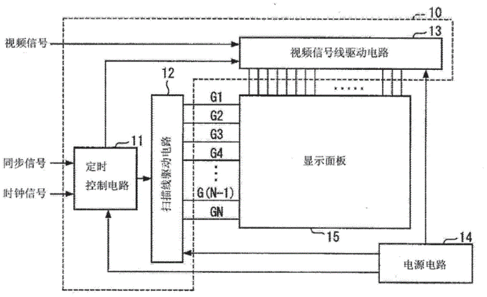
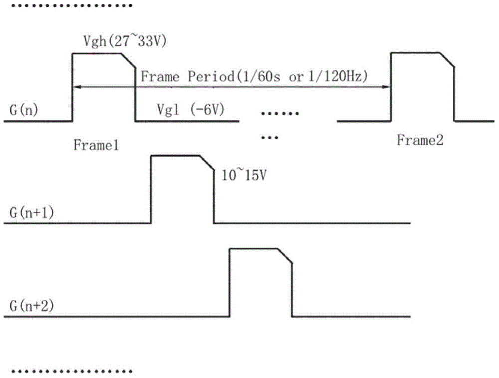
[0065] The scanning line driving circuit outputs a scanning driving signal to each scanning line in the display panel, refer to Figure 4 As shown, the scanning drive signal includes several frame signals distributed periodically, and each frame signal (Frame Period) includes:

[0066] Maintaining the first voltage Vgh of each scan line in the first time period, the first voltage Vgh is a first high-level DC voltage;

[0067] Maintaining a second voltage Vgl with each scan line turned off in the second time period, the second voltage Vgl is an AC voltage, and the second voltage Vgl is a second low-level voltage Vgl1 and a second high-level voltage Vgl2 alternately output;

[0068] Wherein, the first high-level voltage Vgh is greater than the second high-level voltage Vgl2.

[0069] Further, the first voltage also includes a linearly or non-linearly decreasing chamfer voltage located after the first high-level voltage Vgh.

[0070] The chamfering voltage is to solve the feed-...

Embodiment 2

[0077] Further, in this embodiment, the first voltage may only be the first high-level voltage Vgh, excluding the chamfering voltage, and the rest are the same as in Embodiment 1, which will not be repeated here, and the display device can also be improved. Afterimage phenomenon occurs.

Embodiment 3

[0079] In this embodiment, the intermediate potential between the second low-level voltage Vgl2 and the second high-level voltage Vgl2 is a non-zero potential, that is, the absolute value of the voltage between the second low-level voltage Vgl2 and the second high-level voltage Vgl2 Different, for example, the magnitudes of the second low-level voltage Vgl2 and the second high-level voltage Vgl2 are -2V and 6V, or 0V and 8V, or -6V and 2V, or -8V and 0V, etc., as long as the second minimum The level voltage Vgl2 and the second high-level voltage Vgl2 can be alternately transformed to form an AC voltage, and the rest are the same as in Embodiment 1, which can also improve the afterimage phenomenon in the display device.

[0080] Further, in a preferred embodiment, the variation range of the low level signal voltage is -3V˜+3V.

[0081] It can be seen from the above technical solutions that the present invention can effectively improve the leakage current of TFTs in the display ...


PUM


Abstract

The invention discloses a driving method, a driving device and a display device. The driving method is used for driving a display panel, and comprises the step of outputting a scan driving signal for each scan line in the display panel, wherein the scan driving signal comprises a plurality of frames of signals periodically distributed, each frame of signal comprises first voltage and second voltage, the first voltage is used for maintaining gating of each scan line in a first period, and is DC first high-level voltage; the second voltage is used for maintaining switching-off of each scan line in a second period, and is AC voltage, particularly, second low-level voltage and second high-level voltage output alternately; the first high-level voltage is larger than the second high-level voltage. According to the method and the devices provided by the invention, the second voltage for maintaining switching-off of each scan line is converted into the second low-level voltage and the second high-level voltage output alternately, so that the change of leakage current of a TFT in the display panel is effectively improved, image sticking phenomena in the display device are reduced, and the driving method is simple and easy to realize.

Description

technical field [0001] The invention relates to the technical field of liquid crystal display, in particular to a driving method, a driving device and a display device using the driving method. Background technique [0002] "Afterimage" is image sticking (Image Sticking), which is a common bad phenomenon on LCD monitors. It is to keep a static picture on the screen for a long time. Normal deflection under signal voltage control. After a period of time, even if the content of the display screen is changed, traces of the previous still image can still be seen on the screen. Depending on the state of afterimage after screen switching, afterimage can be divided into area sticking and line ship sticking. [0003] When a forward voltage is applied to the liquid crystal molecules, due to the effect of coupling voltage and parasitic voltage, at the falling edge of the Gate signal, that is, when the Gate signal disappears, the charging power of the Pixel has a weak decline process,...

Claims


Application Information

Patent Timeline
Patent Type & Authority Applications(China)
IPC IPC(8): G09G3/36
CPCG09G3/3648G09G2320/0257G09G3/3677G09G3/3688G09G3/3696G09G2310/08G09G2330/00
Inventor 康志聪陈黎暄
Owner TCL CHINA STAR OPTOELECTRONICS TECH CO LTD
Why Eureka
Try Eureka