Sealing joint for transfer between cable and signal cable and manufacturing method thereof

A technology of sealing joints and adapters, which is applied in the direction of cable joints, cable installation, equipment for connecting/terminating cables, etc., and can solve problems such as safety accidents, line transmission failures, and damaged cables

Inactive Publication Date: 2015-08-26
张维秀
View PDF4 Cites 3 Cited by
  • Summary
  • Abstract
  • Description
  • Claims
  • Application Information

AI Technical Summary

Problems solved by technology

[0002] In the power system, the equipment and facilities used to transmit electric energy are mainly divided into cables, distribution stations, and substations. As a common facility for electric power transportation, cables are widely used. The signal cables are erected synchronously. In order to facilitate the shielding connection between the cables and signal cables at the joints, a sealing device for cables and signal cables is specially designed, including a stress tube for connecting cables in the middle, which is set outside one end of the stress tube. Coaxial cable joints, electrodes, extension tubes, etc., the existing cables used to effectively seal the butt joint in the stress tube are specially equipped with an extension tube. The outer diameter of the cable is the same as the inner diameter of the extension tube. After the cable is placed in the extension tube, the appearance It shows that the two have been sealed, but when there is a strong pull, the cable is easy to loosen. When a conductive liquid is immersed, there is a gap between the cables in the stress tube and the conductive liquid, and arcing is easy to occur. occur, thereby damaging the cable and affecting the transmission of electric energy, thereby bringing transmission failure to the entire line and causing a safety accident

Method used


Image

  • Sealing joint for transfer between cable and signal cable and manufacturing method thereof

Examples


Embodiment 1

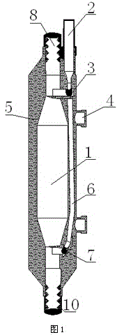
[0027] A sealing joint for connecting cables and signal cables, such as figure 1 As shown, it includes a stress tube 1, a coaxial cable joint 2, a waterproof system 5, and an electrode. The cross section at both ends of the stress tube 1 is smaller than the cross section in the middle, and a first protective layer is arranged around the stress tube 1. In the first A coaxial cable connector 2 is provided on the outside of the protective layer and at one end of the stress tube 1. The coaxial cable connector 2 and the stress tube 1 are connected by electrodes. The waterproof system 5 is sleeved on the stress tube 1 and the coaxial cable. The cable joint 5 also includes an extension pipe 8 , the inner wall of which is provided with an internal thread 10 , and the extension pipe 8 is connected to both ends of the stress pipe 1 .

[0028] When in use, since the inner wall of the extension tube 8 is provided with an internal thread 10, when the cable is connected to the stress tube, ...

Embodiment 2

[0030] This embodiment is further optimized on the basis of the above embodiments, and further, in order to better realize the present invention, as figure 1 As shown, it includes a stress tube 1, a coaxial cable joint 2, a waterproof system 5, and an electrode. The cross section at both ends of the stress tube 1 is smaller than the cross section in the middle, and a first protective layer is arranged around the stress tube 1. In the first A coaxial cable connector 2 is provided on the outside of the protective layer and at one end of the stress tube 1. The coaxial cable connector 2 and the stress tube 1 are connected by electrodes. The waterproof system 5 is sleeved on the stress tube 1 and the coaxial cable. On the cable joint 5; also includes an extension tube 8, the inner wall of the extension tube 8 is provided with an internal thread 10, and the extension tube 8 is connected to both ends of the stress tube 1; it also includes a test hole 4, and the opening of the test hol...

Embodiment 3

[0032] This embodiment is further optimized on the basis of embodiment 1, as figure 1 As shown, further, in order to better realize the present invention, it includes a stress tube 1, a coaxial cable joint 2, a waterproof system 5, and an electrode. There is a first protective layer, and a coaxial cable connector 2 is arranged on the outside of the first protective layer and at one end of the stress tube 1, and the coaxial cable connector 2 and the stress tube 1 are connected by electrodes, and the waterproof The system 5 is sleeved on the stress tube 1 and the coaxial cable joint 5; it also includes an extension tube 8, the inner wall of the extension tube 8 is provided with internal threads 10, the extension tube 8 is connected to both ends of the stress tube 1, and the electrodes Including a first electrode 3 and a second electrode 7, the first electrode is located at the side of the coaxial cable joint 2 and connected to the stress tube 1, the second electrode 7 is located...


PUM


Abstract

The invention discloses a sealing joint for transfer between a cable and a signal cable, which comprises a stress tube, a coaxial cable joint, a waterproof system, and an electrode, wherein cross sections at two ends of the stress tube are smaller than the cross section in the middle part; a first protection layer is arranged around the stress tube; the coaxial cable joint is arranged at the outer side of the first protection layer and located at one end of the stress tube; the coaxial cable joint and the stress tube are connected via the electrode; and the waterproof system sleeves the stress tube and the coaxial cable joint. The invention also discloses a sealing joint manufacturing method. in order to solve defects that in the condition of force pulling in the prior art, intrusion of a foreign body happens due to looseness, an arcing phenomenon thus happens between cables in the stress tube, and electric energy transmission is influenced, a new connection structure is designed, separation between the cable and the sealing joint under the pulling force can be effectively avoided, the arcing phenomenon due to immersion of conductive liquid can be prevented from happening, and safety accidents can be prevented from happening.

Description

technical field [0001] The invention relates to the field of electric power technology, in particular to a sealing joint for connecting cables and signal cables and a manufacturing method thereof. Background technique [0002] In the power system, the equipment and facilities used to transmit electric energy are mainly divided into cables, distribution stations, and substations. As a common facility for electric power transportation, cables are widely used. The signal cables are erected synchronously. In order to facilitate the shielding connection between the cables and signal cables at the joints, a sealing device for cables and signal cables is specially designed, including a stress tube for connecting cables in the middle, which is set outside one end of the stress tube. Coaxial cable joints, electrodes, extension tubes, etc., the existing cables used to effectively seal the butt joint in the stress tube are specially equipped with an extension tube. The outer diameter o...

Claims


Application Information

Patent Timeline
Patent Type & Authority Applications(China)
IPC IPC(8): H02G15/18
CPCH02G15/085H02G1/14H02G15/184
Inventor 张维秀
Owner 张维秀
Why Eureka
Try Eureka