
Falling film evaporator

A technology of falling film evaporator and distribution head, which is applied in evaporator accessories, evaporation, evaporator adjustment/control, etc. It can solve the problem that the conical distribution head cannot stick to the tube wall, the life of the liquid pipeline is short, and the heat dissipation of the distribution head is uneven. problems, to avoid uneven heating, prolong life, and facilitate the effect of uniform distribution

Active Publication Date: 2017-10-20
SUZHOU ZHUOQUN TITANIUM NICKEL EQUIP
View PDF5 Cites 3 Cited by
  • Summary
  • Abstract
  • Description
  • Claims
  • Application Information

AI Technical Summary

Problems solved by technology

[0002] In the falling film evaporator in the prior art, the distribution heads used for liquid diversion often have the problems of uneven heat dissipation and short service life of the liquid pipeline; in addition, the distribution heads in the existing falling film evaporators are conical, but the conical The shape distribution head cannot be close to the pipe wall, resulting in poor film-forming effect and low efficiency of the liquid on the pipe wall, as well as the problem of uneven heating of the pipe wall and high damage rate, but there is no related device in the prior art that can solve this problem

Method used


Image

  • Falling film evaporator
  • Falling film evaporator
  • Falling film evaporator

Examples


Embodiment 1

[0025] This example illustrates the specific structure of the falling film evaporator of the present invention.

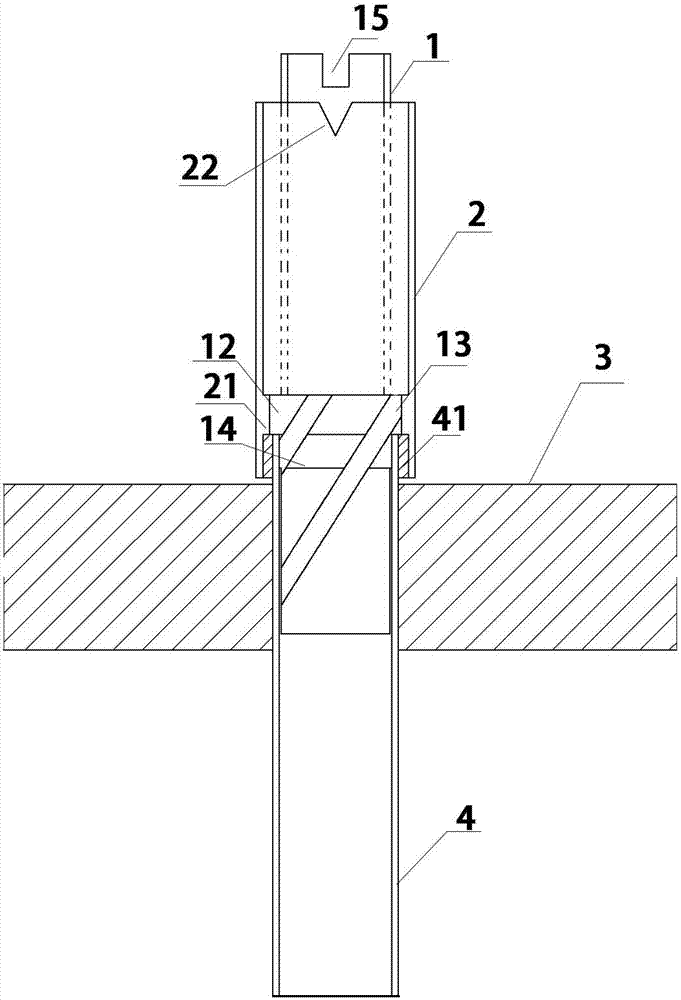
[0026] Such as Figure 1-6 The falling film evaporator shown includes a distribution head 1, a pipe sleeve 2, a tube plate 3, a tube 4 and an externally threaded tube 41 provided outside the upper end of the tube 4;

[0027] The tube plate 3 is provided with several through holes, the tube array 4 is inserted into the through hole and connected with the tube plate 3, and the upper end of the tube array is provided with an externally threaded tube 41;

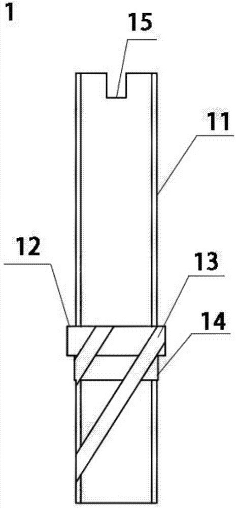
[0028] The specific structure of distribution header 1 is as follows: Figure 3-5 As shown, the main body of the distribution head 1 is a hollow tube 11, and the top of the hollow tube 11 is provided with several rectangular openings 15; The body of the hollow tube 11 is arranged as a ring-shaped protrusion; the second boss 14 is also provided below the boss 12, and the second boss 14 is arranged around the body of...


PUM


Abstract

The invention relates to a falling film evaporator. The falling film evaporator is characterized in that in the falling film evaporator, a tube plate is provided with a plurality of through holes, a tubulation is inserted into the through holes and is connected to the tube plate, the outer part of the upper end of the tubulation is provided with an external thread pipe, a distribution head is inserted into the tubulation and is connected to the tubulation, the main body of the distribution head is a hollow circular tube, the lower part of the outer wall of the hollow circular tube is provided with an annular first boss, the annular first boss is provided with a plurality of opening grooves, the grooves helically extend down to the bottom of the tube wall from the upper edge of the annular first boss along the annular first boss and the outer wall of the hollow circular tube and is used for diversion, a casing pipe wraps the distribution head and is a hollow circular tube, the inner wall of the casing pipe corresponding to the first boss is provided with an annular inner boss, the inner diameter of the inner boss fits to the outer diameter of the first boss, the upper end of the casing pipe is connected to the outer wall of the hollow circular tube of the distribution head through spot welding and the inner wall of the lower part of the annular inner boss of the casing pipe tightly fits to the outer wall of the external thread pipe. The liquid in the tubulation of the falling film evaporator can easily form a film so that the pipe wall is uniformly heated, the tubulation damage rate is reduced and a falling film evaporator service life is prolonged.

Description

technical field [0001] The invention belongs to the field of chemical manufacturing, and in particular relates to a falling film evaporator. Background technique [0002] In the falling film evaporator in the prior art, the distribution heads used for liquid diversion often have the problems of uneven heat dissipation and short service life of the liquid pipeline; in addition, the distribution heads in the existing falling film evaporators are conical, but the conical The shape distribution head cannot be close to the pipe wall, resulting in poor film-forming effect and low efficiency of the liquid on the pipe wall, as well as the problem of uneven heating of the pipe wall and high damage rate, but there is no related device in the prior art that can solve this problem . Contents of the invention [0003] The purpose of the present invention is to overcome the defects in the prior art and provide a falling film evaporator. [0004] In order to realize the above-mentioned...

Claims


Application Information

Patent Timeline
Patent Type & Authority Applications(China)
IPC IPC(8): B01D1/22B01D1/30B01D1/00
CPCB01D1/0082B01D1/22B01D1/30Y02A20/124
Inventor 潘云祥
Owner SUZHOU ZHUOQUN TITANIUM NICKEL EQUIP
Learn More