
A wireless charging method, device and system

A technology of wireless charging and charging request, applied in circuit devices, battery circuit devices, secondary battery charging/discharging, etc., can solve the problems of incapable of wireless charging of electrical equipment, cumbersome wireless charging operation, low flexibility and low charging efficiency, etc.

Active Publication Date: 2018-08-10
BAIDU ONLINE NETWORK TECH (BEIJIBG) CO LTD
View PDF4 Cites 0 Cited by
  • Summary
  • Abstract
  • Description
  • Claims
  • Application Information

AI Technical Summary

Problems solved by technology

In the prior art, the user needs to manually place the electric device at a fixed position, and manually align the electric device with the power supply device, otherwise the power supply device will not be able to wirelessly charge the electric device due to misalignment
[0003] However, in the prior art, the user is required to manually set the position of the electric device, and the user is required to manually perform an alignment operation between the electric device and the power supply device, resulting in cumbersome wireless charging operations in the prior art. The charging range of charging is relatively small, and the flexibility and charging efficiency are relatively low

Method used


Image

  • A wireless charging method, device and system
  • A wireless charging method, device and system
  • A wireless charging method, device and system

Examples


Embodiment 1

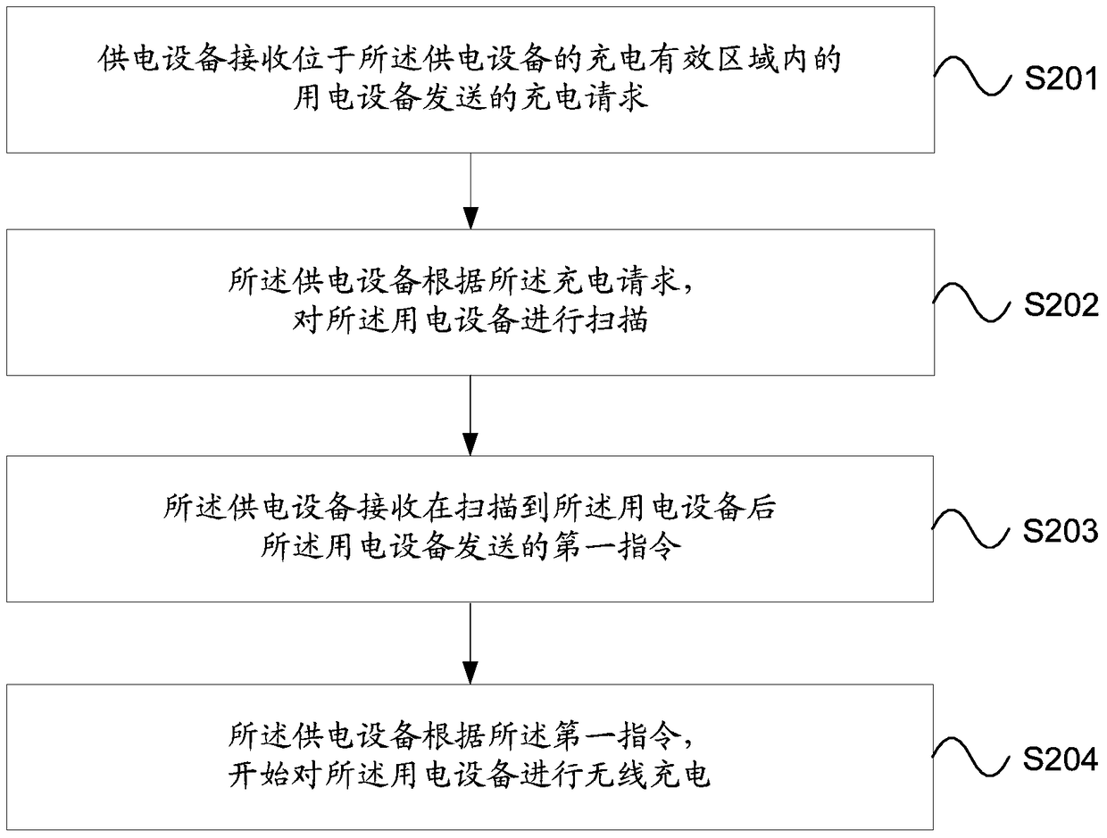
[0104] The embodiment of the present invention provides a wireless charging method, please refer to figure 2 , which is a schematic flow chart of Embodiment 1 of the wireless charging method provided by the embodiment of the present invention. This embodiment implements the wireless charging method on the side of the power supply device. As shown, the method includes the following steps:

[0105] S201. The power supply device receives a charging request sent by a power consumption device located in an effective charging area of ​​the power supply device.

[0106] S202. The power supply device scans the power consumption device according to the charging request.

[0107] S203. The power supply device receives a first instruction sent by the power consumption device after the power consumption device is scanned.

[0108] S204. The power supply device starts to wirelessly charge the power consumption device according to the first instruction.

[0109] Please refer to image ...

Embodiment 2

[0151] Please refer to Figure 5 , which is a schematic flow chart of Embodiment 2 of the wireless charging method provided by the embodiment of the present invention. This embodiment implements the wireless charging method on the electric device side. As shown, the method includes the following steps:

[0152] S501. A power consumption device located in an effective charging area of ​​the power supply device sends a charging request to the power supply device, so that the power supply device scans the power consumption device according to the charging request.

[0153] S502. After the power-consuming device is scanned, the power-consuming device sends a first instruction to the power supply device, so that the power supply device starts to wirelessly charge the power-consuming device according to the first instruction. .

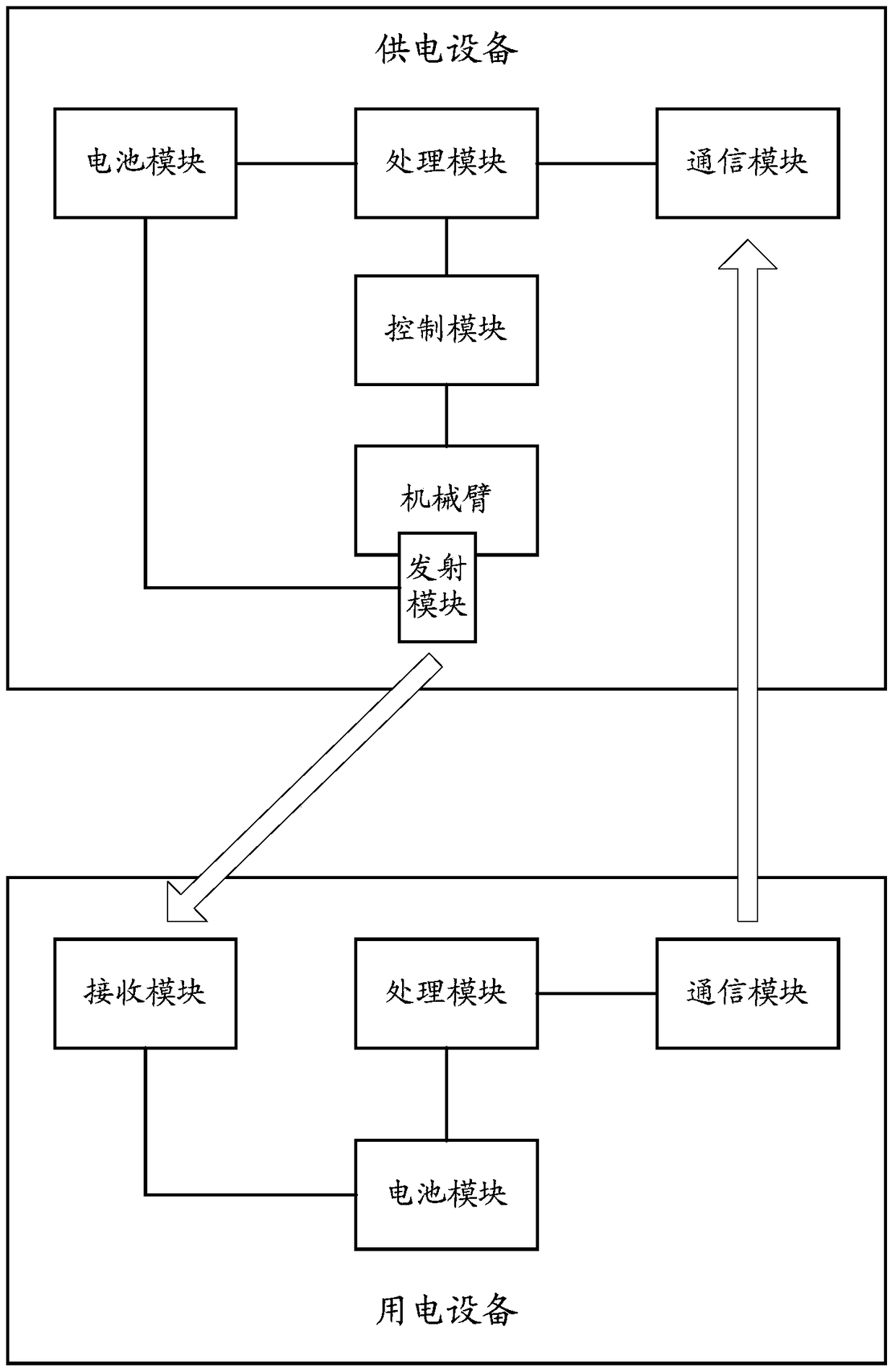
[0154] Such as image 3 As shown, the electric device may include: a communication module, a processing module, a receiving module and a battery module....


PUM


Abstract

The invention provides a wireless charging method, device and system. The method comprises that a power supply device receives a charging request sent by electric equipment which is positioned in an effective charging area of the power supply device; the power supply device scans the electric equipment according to the charging request; the power supply device receives a first instruction sent by the electric equipment after the electric equipment is scanned; and the electric equipment is charged wirelessly according to the first instruction. Thus, the electric equipment can be scanned automatically, wireless charging is carried out automatically after the electric equipment is scanned, the scope of wireless charging is broadened, and the flexibility and charging efficiency are improved.

Description

【Technical field】 [0001] The present invention relates to the technical field of wireless power, in particular to a wireless charging method, device and system. 【Background technique】 [0002] At present, in the wireless charging technology, the energy transmission between the electrical equipment and the power supply equipment is mainly through infrared or electromagnetic waves, so as to realize the wireless charging of the electrical equipment. In the prior art, the user needs to manually place the electric device at a fixed position, and manually align the electric device with the power supply device, otherwise the power supply device will not be able to wirelessly charge the electric device due to misalignment. [0003] However, in the prior art, the user is required to manually set the position of the electric device, and the user is required to manually perform an alignment operation between the electric device and the power supply device, resulting in cumbersome wirel...

Claims


Application Information

Patent Timeline
Patent Type & Authority Patents(China)
IPC IPC(8): H02J7/00H02J50/00H01M10/44
CPCY02E60/10
Inventor 杨开睿汤巍敏
Owner BAIDU ONLINE NETWORK TECH (BEIJIBG) CO LTD
Learn More