Light guide plate comprising decoupling elements

A technology of output coupling and light guide plate, which is applied in the field of planar light distribution modules, can solve problems such as precise orientation, increased production cost, and high cost, and achieve the effects of uniform illumination, simple production, and low structural height

Inactive Publication Date: 2015-08-26
COVESTRO DEUTSCHLAND AG
View PDF20 Cites 5 Cited by
  • Summary
  • Abstract
  • Description
  • Claims
  • Application Information

AI Technical Summary

Problems solved by technology

where the color selection grid is spatially matched to the pixels of the light-transmissive digital light modulator, which is prohibitively expensive for increasingly high-resolution display panels
[0017] In addition, the use of the above method in displays with increasing resolution also increases the production cost
Therefore, the precise orientation between the grid points and the smaller and smaller pixels on the display also poses a particular challenge

Method used


Image

  • Light guide plate comprising decoupling elements
  • Light guide plate comprising decoupling elements
  • Light guide plate comprising decoupling elements

Examples


Embodiment Construction

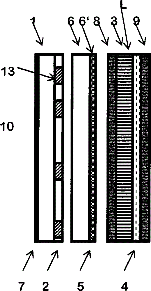
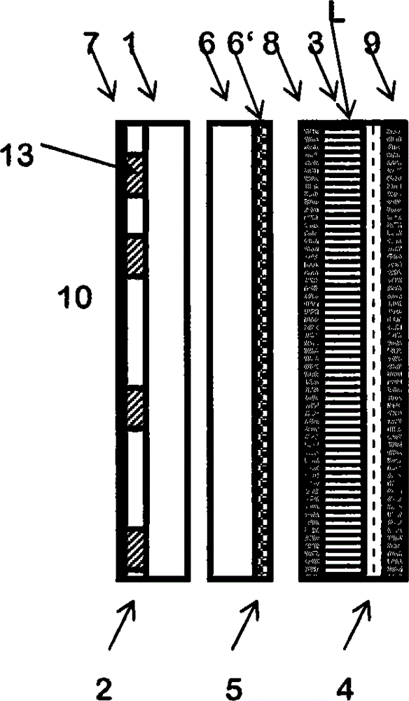
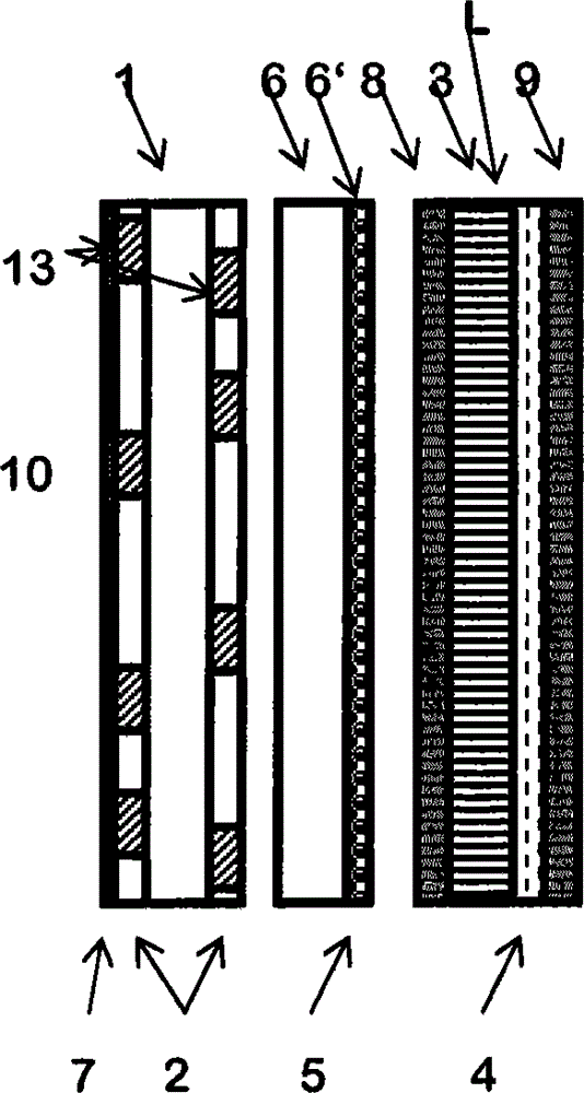
[0098] According to the first preferred embodiment, such as figure 1 Schematically shown, a display 10 according to the invention consists of a light guide plate 1 and an outcoupling device 2 comprising a holographic optical element 13 in the form of a volume grid in transmissive mode. The volume grid has an extent of, for example, 300 μm, 400 μm or even 1000 μm in at least one spatial axis running parallel to the surface of the output coupling. Therein, the light guide plate 1 and the outcoupling device 2 are in optical contact with each other. As shown, the volume grids are irregularly spaced from each other, wherein the invention is not limited to this arrangement.

[0099] The light guide plate 1 consists of a transparent plastic, preferably an essentially birefringent-free amorphous thermoplastic, particularly preferably polymethyl methacrylate or polycarbonate. Wherein, the thickness of the light guide plate is between 50 and 3000 μm, preferably between 200 and 2000 μm...


PUM


Abstract

The invention relates to a planar light distribution module for a display, comprising a light guide plate through which light coupled in via at least one side face can propagate by means of total reflection, and at least one out-coupling device (2), which is applied on one or both of the main faces of the light guide plate (1), is in optical contact therewith and has a multiplicity of holographic optical elements (13) formed therein, which are configured in such a way that they can couple light out of the light guide plate (1), the light distribution module being characterized in that the holographic optical elements (13), independently of one another, have an extent of at least 300 μm in at least one spatial axis extending parallel to the surface of the out-coupling device (2). The invention furthermore relates to an optical display, in particular an electronic display.

Description

technical field [0001] The invention relates to a planar light distribution module for a display screen, comprising a light guide plate through which light that can be coupled via at least one side can propagate by means of total reflection, and comprising at least one planar outcoupling device, The outcoupling device is mounted on one or both of the major faces of the light guide plate in optical contact with the light guide plate and includes a plurality of holographic optical elements constructed therein, the holographic optical elements being such designed such that it is possible to outcouple light from the light guide plate. The invention also relates to an optical display, in particular to an optoelectronic display with a light distribution module. Background technique [0002] Liquid crystal displays have found wide applications. It comes in various sizes. From small LC displays in mobile phones, game consoles, to medium-sized displays in laptops, tablets, desktop...

Claims


Application Information

Patent Timeline
Patent Type & Authority Applications(China)
IPC IPC(8): G02B6/00F21V8/00
CPCG02B6/0061G02B6/0035G02B6/0051
Inventor T·费克F-K·布鲁德R·哈根G·瓦尔策T·罗勒H·贝内特D·赫内尔M-S·魏泽W·霍海泽尔
Owner COVESTRO DEUTSCHLAND AG
Why Eureka
Try Eureka