Drive mechanism with flexible clamp
A driving mechanism and clamping technology, used in auxiliary devices, applications, auxiliary welding equipment, etc., can solve the problems of scratches on the surface of the pipeline, damage to the fixture, and small contact area between the fixture and the surface of the pipeline, to prevent left and right play and slippage. , the effect of reducing damage
- Summary
- Abstract
- Description
- Claims
- Application Information
AI Technical Summary
Problems solved by technology
Method used
Image

Examples
Embodiment 1
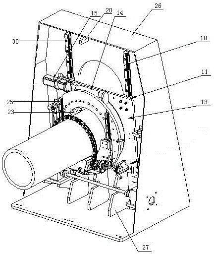
[0024] Embodiment 1, with Figure 4 Take a steel pipe with a middle diameter of 450mm as an example.
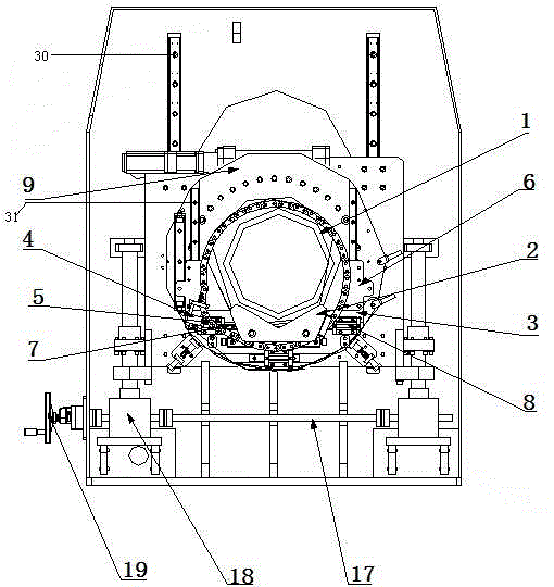
[0025] The first step is to put the end of the steel pipe 1 to be welded on the V-shaped block 2, and then tie the steel pipe 1 with the chain 5 and lock it with the chain locker 4. At this time, the steel pipe 1 and the V-shaped block 2 are fixed together by the chain 5 , since then the flexible clamping of the steel pipe has been completed;
[0026] In the second step, start the servo motor 15 and drive the rotary part 14 to rotate through the gearbox, the rotary part 14 drives the connecting part 9 to rotate, and the steel pipe clamped on the connecting part 9 rotates, because there are two pairs of mutually perpendicular straight lines on the connecting part 9 The guide rail moving pair, the non-straight Φ450mm steel pipe 1 and the V-shaped block 2 can freely slide on the horizontal linear guide 7 and the vertical linear guide 25 during the rotation process (for the spec...
Embodiment 2
[0027] Embodiment 2, with Figure 5 Take a steel pipe with a middle diameter of 400mm as an example.
[0028] The first step is to put the end of the steel pipe 1 to be welded on the V-shaped block 2, then tie the steel pipe 1 with the chain 5 and lock it with the chain locker 4 (if the steel pipe is long, you can put the other end on the auxiliary support frame) , since then the flexible clamping of the steel pipe has been completed;
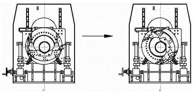
[0029] In the second step, start the servo motor 15 and drive the rotary part 14 to rotate through the gearbox, the rotary part 14 drives the connecting part 9 to rotate, and the steel pipe clamped on the connecting part 9 rotates, because there are two pairs of mutually perpendicular straight lines on the connecting part 9 The guide rail moving pair, the non-straight Φ400mm steel pipe 1 can freely move along the radial direction and perpendicular to each other during the rotation process (for the specific movement process, refer to image 3 ...
Embodiment 3
[0030] Embodiment 3, with Image 6 Take a steel pipe with a middle diameter of 350mm as an example.
[0031] The first step is to put the end of the steel pipe 1 to be welded on the V-shaped block 2, then tie the steel pipe 1 with the chain 5 and lock it with the chain locker 4 (if the steel pipe is long, you can put the other end on the auxiliary support frame) , since then the flexible clamping of the steel pipe 1 is completed;
[0032] In the second step, start the servo motor 15 and drive the rotary part 14 to rotate through the gearbox. The rotary part 14 drives the connecting part 9 to rotate, and the steel pipe 1 clamped on the connecting part 9 rotates. The linear guide rail moving pair, the non-straight Φ350mm steel pipe 1 can freely move along the radial direction and perpendicular to each other during the rotation process (for the specific movement process, refer to image 3 ), the two radial movements compound to play the role of automatic centering.
PUM
| Property | Measurement | Unit |
|---|---|---|
| Diameter | aaaaa | aaaaa |
| Diameter | aaaaa | aaaaa |
| Diameter | aaaaa | aaaaa |
Abstract
Description
Claims
Application Information
 - R&D
- Intellectual Property
- Life Sciences
- Materials
- Tech Scout
- Unparalleled Data Quality
- Higher Quality Content
- 60% Fewer Hallucinations
Browse by: Latest US Patents, China's latest patents, Technical Efficacy Thesaurus, Application Domain, Technology Topic, Popular Technical Reports.
© 2025 PatSnap. All rights reserved.Legal|Privacy policy|Modern Slavery Act Transparency Statement|Sitemap|About US| Contact US: help@patsnap.com