A spring self-resetting two-stage hydraulic tensioner with counting function
A hydraulic tensioner and self-reset technology, applied in the direction of instruments, manufacturing tools, counting mechanisms/items, etc., can solve the problems of easy to get stuck, inaccurate counting, etc. Use effective effects
- Summary
- Abstract
- Description
- Claims
- Application Information
AI Technical Summary
Problems solved by technology
Method used
Image
Examples
Embodiment 1
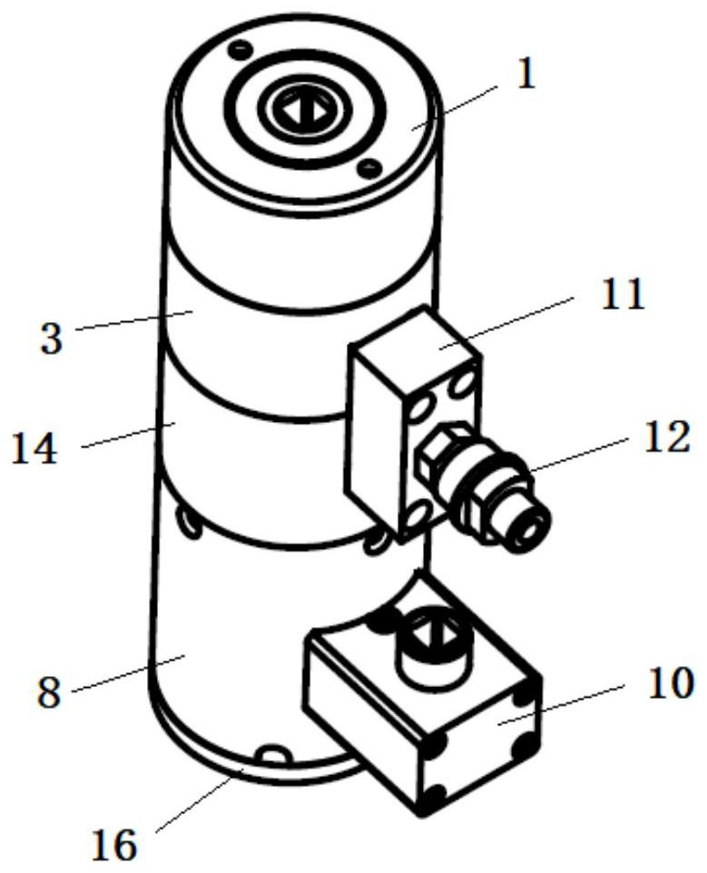
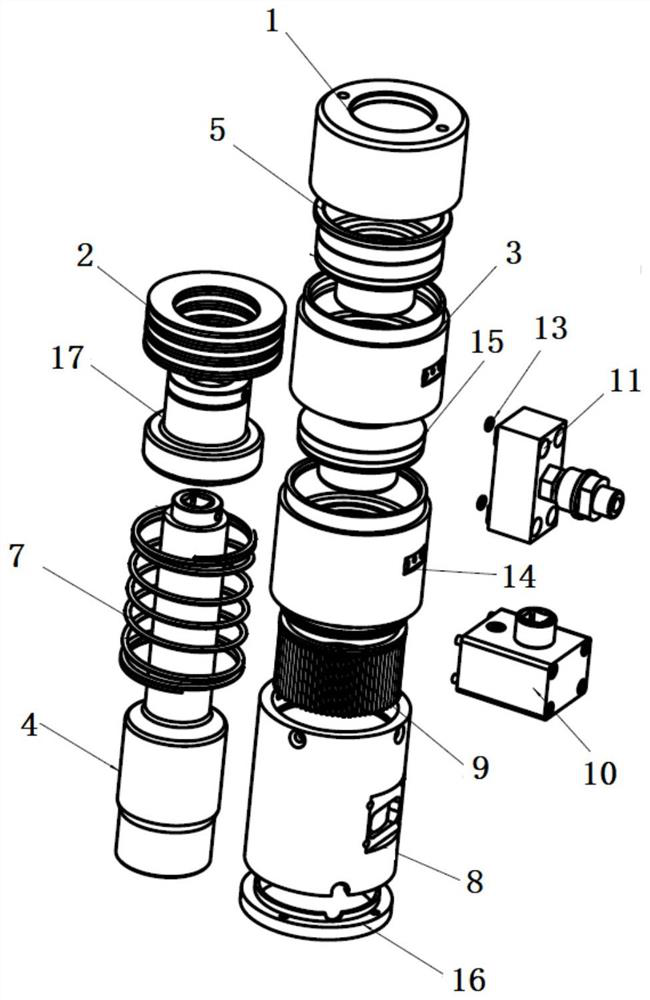
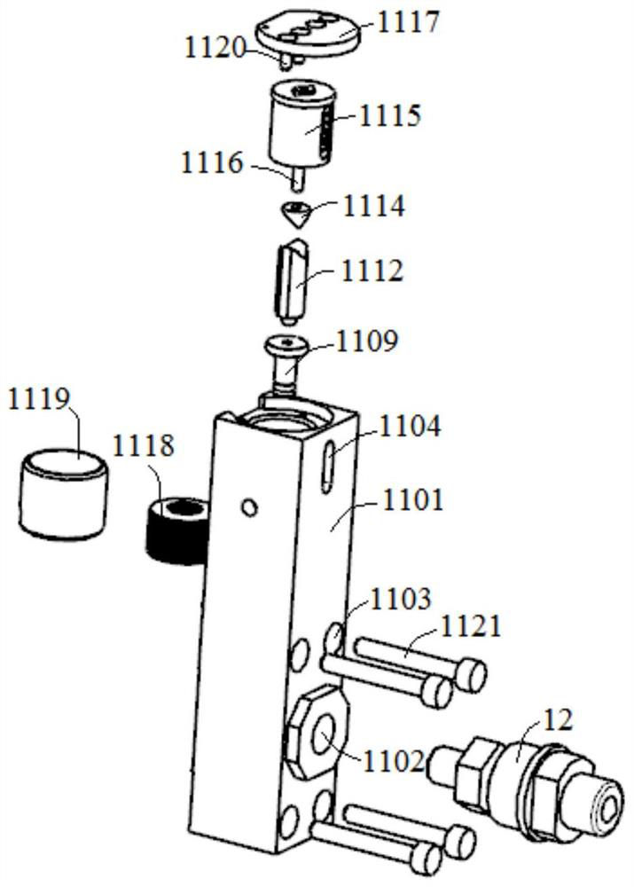
[0039] A kind of spring self-resetting two-stage hydraulic stretching with counting function in this embodiment, such as figure 1 and figure 2 As shown, it includes a stretcher main body and a counting device 11 installed on the side wall of the stretcher main body. The stretcher main body includes a pull rod 4 and a first oil cylinder 3 and a second oil cylinder 14 connected up and down. The pull rod 4 is set In the two oil cylinders, the first piston 5 and the second piston 15 are respectively arranged between the pull rod 4 and the two oil cylinders, the bottom of the first piston 5 is against the top of the second piston 15, and the upper end of the pull rod 4 is fixedly installed Threaded cover 17 is arranged. The present invention greatly improves the working tension by designing two oil cylinders, can effectively reduce the diameter of the stretcher, and is more suitable for use in working conditions with narrow spaces.
[0040] The counting device 11 is installed on...
Embodiment 2
[0046] A spring self-resetting two-stage hydraulic tensioner with counting function in this embodiment is basically the same in structure as in Embodiment 1, the main difference being: figure 2 and Figure 6 As shown, the main body of the tensioner includes an end cover 1, a first oil cylinder 3, a second oil cylinder 14, a support sleeve 8, a pull rod 4, a high-pressure joint 12 and a threaded sleeve 17 connected successively from top to bottom. 1 is a cylindrical shell with a through hole processed at the center of its top. The diameter of the through hole matches the top of the pull rod 4. The top of the pull rod 4 is installed in the through hole, and its upper end is fixed with a threaded sleeve 17 by bolts. The first disc spring 2 can be placed in the inner cavity of the end cover 1 , and the first disc spring 2 is sleeved on the threaded sleeve 17 . Such as Figure 7 As shown, the lower part of the threaded sleeve 17 protrudes outward to form a boss, the bottom of th...
Embodiment 3
[0054] A spring self-resetting two-stage hydraulic tensioner with counting function in this embodiment is basically the same in structure as in Embodiment 2, the difference mainly lies in: Figure 8-10 As shown, the shifting gear assembly 10 includes a gear case, a first gear 1002, a second gear 1003 and an inner hexagonal ring gear 9, the first gear 1002 and the second gear 1003 are installed in the gear case, and the first The second gear 1003 is externally meshed with the first gear 1002 and the inner hexagonal ring gear 9 respectively. The gear box body has an integrally formed structure. Improve the overall strength and sealing of the gearbox, and it is not easy to crack in frequent use occasions.
[0055] Such as Figure 9 As shown, a positioning block 1008 is provided on the side of the gear box close to the hydraulic stretcher, and a positioning slot is provided at the corresponding position where the gear box is installed on the stretcher, and the positioning block 1...
PUM
 Abstract
Description
Claims
Application Information
 - R&D
- Intellectual Property
- Life Sciences
- Materials
- Tech Scout
- Unparalleled Data Quality
- Higher Quality Content
- 60% Fewer Hallucinations
Browse by: Latest US Patents, China's latest patents, Technical Efficacy Thesaurus, Application Domain, Technology Topic, Popular Technical Reports.
© 2025 PatSnap. All rights reserved.Legal|Privacy policy|Modern Slavery Act Transparency Statement|Sitemap|About US| Contact US: help@patsnap.com


