Universal swinging type conveying belt error correcting device

A deviation correction device and conveyor belt technology, applied in the direction of conveyors, conveyor objects, transportation and packaging, etc., can solve the problems of large rotational resistance at the middle hinge, inflexible movement, and unstable swing of the swing roller frame, and achieve Space swing, improve the effect of deviation correction, and improve the effect of force condition

Active Publication Date: 2015-09-02
XUZHOU HUIKE AUTOMATION ENG
View PDF15 Cites 6 Cited by
  • Summary
  • Abstract
  • Description
  • Claims
  • Application Information

AI Technical Summary

Problems solved by technology

Under normal circumstances, this type of deviation correction device has a large rotational resistance at the middle hinge, and the swing idler frame does not swing smoothly, and the movement is often inflexible.

Method used


Image

  • Universal swinging type conveying belt error correcting device
  • Universal swinging type conveying belt error correcting device
  • Universal swinging type conveying belt error correcting device

Examples


Embodiment 1

[0043] Refer to attached Figure 1 to Figure 7 .

[0044] The technical solution adopted by the present invention to solve its technical problems is:

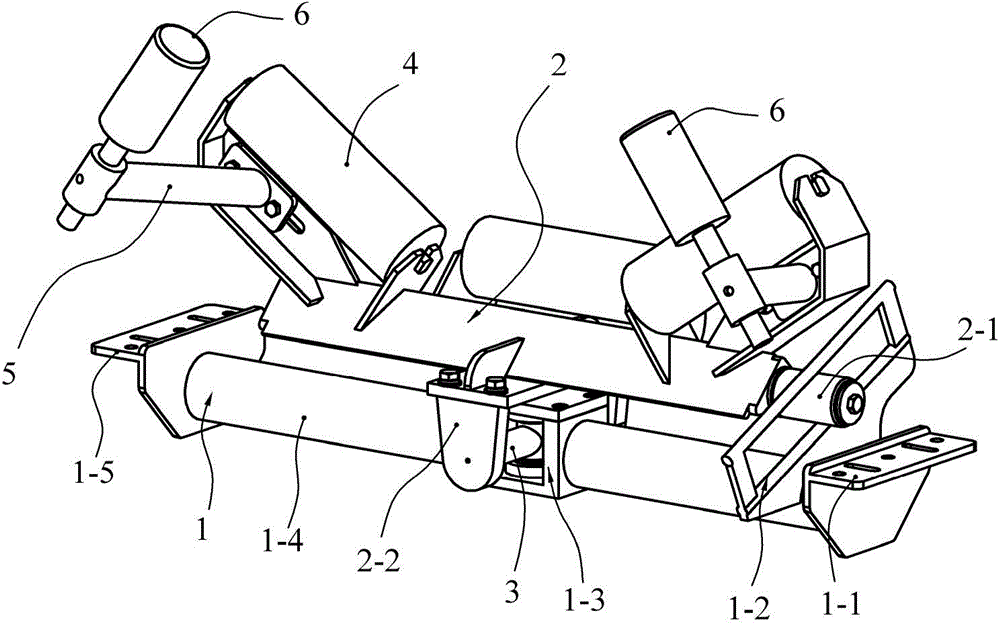
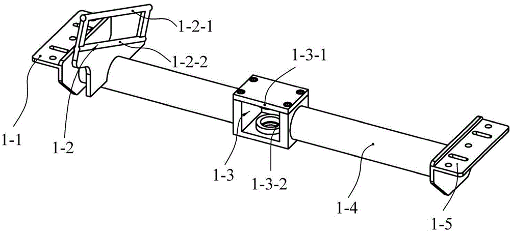
[0045] Such as figure 1 As shown, the first embodiment of the universal swing conveyor belt correction device includes a bottom beam 1, a swing idler frame 2, an idler roller 4, a guide roller frame 5, and a guide roller 6, and the idler roller 4 is clamped on the swing idler frame 2, the guide rollers are symmetrically installed on both ends of one side of the swing roller frame 2 through the guide roller frame 5; Universal structure; the supporting connector 3 is hinged with the bottom beam 1 to form a rotating pair, and the supporting connecting member 3 is hinged with the swing idler frame 2 to form a rotating pair, and the axes of the two rotating pairs are orthogonal; the One end of the bottom beam 1 is provided with a longitudinal oblique guide unit, and one end of the swing roller frame 2 is provided with an end guid...

Embodiment 2

[0053] Refer to attached Figure 8 .

[0054] The structure of the second embodiment is similar to that of the first embodiment, the difference is that the oblique guide unit of the bottom beam 1 of the second embodiment adopts a helical curved groove 1-6, and the helical curved groove 1-6 includes an upper curved track 1-6-1 and the next track 1-6-2. The design of the spiral curved groove 1-6 can reduce the axial displacement of the guide roller 2-1 of the swing idler frame 2 relative to the inclined guide unit when moving in the spiral curved groove 1-6.

Embodiment 3

[0056] Refer to attached Figure 9 , 10 .

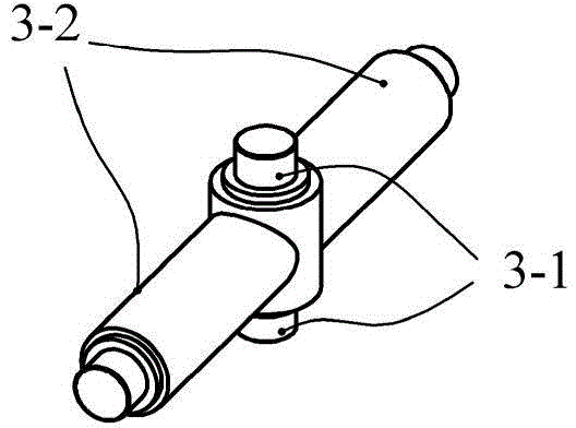
[0057] Figure 9 In the third embodiment shown, the swing idler frame 2 and the bottom beam 1 are connected together through the supporting connector 3 to form a universal structure. Such as Figure 10 As shown, the support connector 3 includes a vertical connector and a horizontal connector, and the vertical connectors are connected orthogonally in the middle of the horizontal connector to form a T-shaped structure; the vertical connector is a vertical half Axis 3-3, the horizontal connecting piece is the horizontal axis 3-2; the two ends of the bottom beam 1 are symmetrically provided with two longitudinal oblique guide units, and the oblique guide units adopt oblique guide rails, which are respectively denoted as oblique Guide rail one 1-7 and inclined guide rail two 1-9, described inclined guide rail is higher than the other end at one end in longitudinal direction; The middle part of described bottom beam 1 is provided with ...


PUM


Abstract

The invention discloses a universal swinging type conveying belt error correcting device. The universal swinging type conveying belt comprises a bottom transverse beam, a swinging idler frame and a support connecting piece, wherein an idler is clamped on the swinging idler frame; at least one end of the bottom transverse beam is provided with a longitudinal inclined guide unit; one end of the inclined guide unit is higher than the other end; at least one end of the swinging idler frame is provided with an end guide part; the middle part of the swinging idler frame and the middle part of the bottom transverse beam are connected through the support connecting piece, thereby constructing a universal structure; the support connecting piece is hinged to the bottom transverse beam, thereby constructing a rotation pair; the support connecting piece is hinged to the idler frame, thereby constructing a rotation pair; the axes of the two rotation pairs are orthogonal to each other; the end guide part on the swinging idler frame is limited and guided by the inclined guide unit on the bottom transverse beam. The universal swinging type conveying belt error correcting device is applied to error correction of a conveying belt of a belt conveyer; the swinging idler frame is guided by the inclined guide unit and swings in the vertical direction while swinging in the horizontal direction, thereby forming universal swinging, and error correction of the conveying belt is realized under the coaction of the friction force and the gravity.

Description

technical field [0001] The invention relates to a universal swing conveyor belt deviation correcting device, which belongs to the technical field of belt conveyors. Background technique [0002] Belt deviation of belt conveyor is a common phenomenon. There are many factors causing deviation, such as deformation of conveyor frame, improper installation of idler rack, improper joint of conveyor belt, large damage resistance of some idler rollers, wear of belt, etc. . Installing a self-aligning roller set or a special correction device is one of the solutions to solve the deviation of the conveyor belt. At present, the middle part of the mounting bracket of the self-aligning roller group (deviation correction device) that is common on the market is hinged with the middle part of the swinging roller frame in the vertical direction to form a rotating pair, and the swinging roller frame is usually driven by a side vertical roller or a linkage mechanism. Swing, when the conveyor ...

Claims


Application Information

Patent Timeline
Patent Type & Authority Applications(China)
IPC IPC(8): B65G39/16
CPCB65G15/64B65G39/16
Inventor 李允旺代素梅田丰
Owner XUZHOU HUIKE AUTOMATION ENG
Why Eureka
Try Eureka