Shear-reinforced structure of steel beams

A technology for strengthening structures and steel beams, applied in truss structures, joists, girders, etc., can solve problems such as large thickness, difficulty in procurement and welding, and impact on building functions, so as to improve shear bearing capacity and avoid procurement and welding. The effect of difficult, simple construction

Active Publication Date: 2017-06-13
TONGJI UNIV
View PDF7 Cites 0 Cited by
  • Summary
  • Abstract
  • Description
  • Claims
  • Application Information

AI Technical Summary

Problems solved by technology

[0006] However, if the height of the section is increased, the heightened steel girder will inevitably affect the realization of the building function; and if the web of the steel girder is thickened, it is often difficult to purchase and weld due to the thickness

Method used


Image

  • Shear-reinforced structure of steel beams
  • Shear-reinforced structure of steel beams
  • Shear-reinforced structure of steel beams

Examples


Embodiment 1

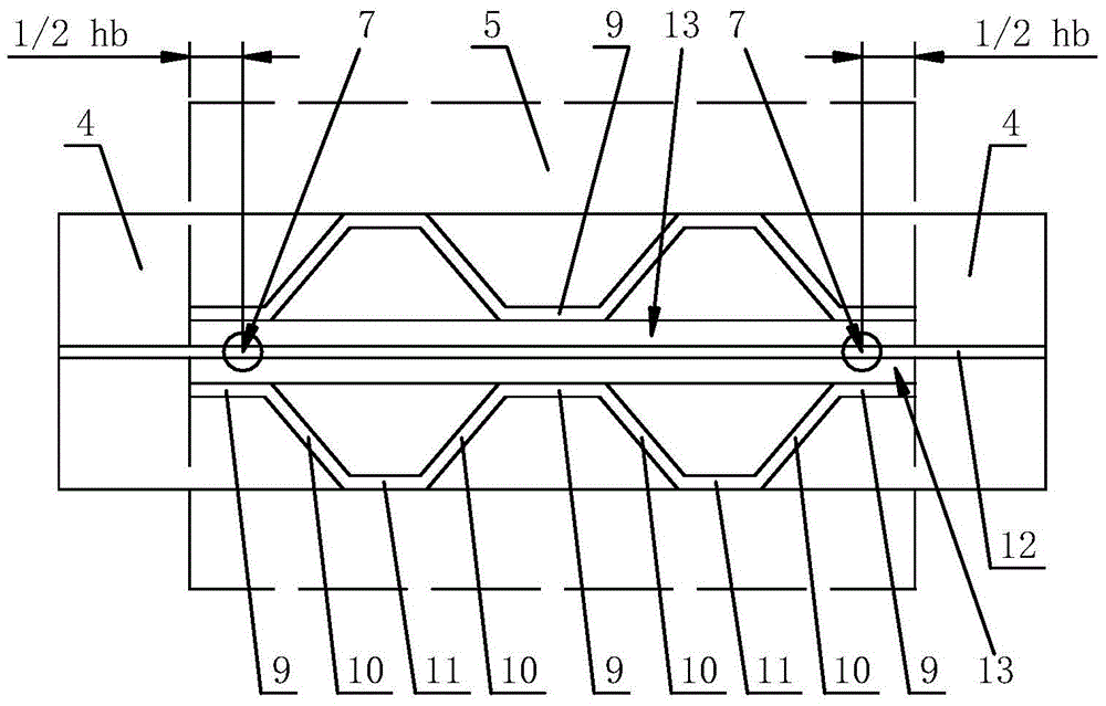
[0045] According to the requirement of shear bearing capacity, the required thickness δ of the corrugated steel plate is more than 20 mm.

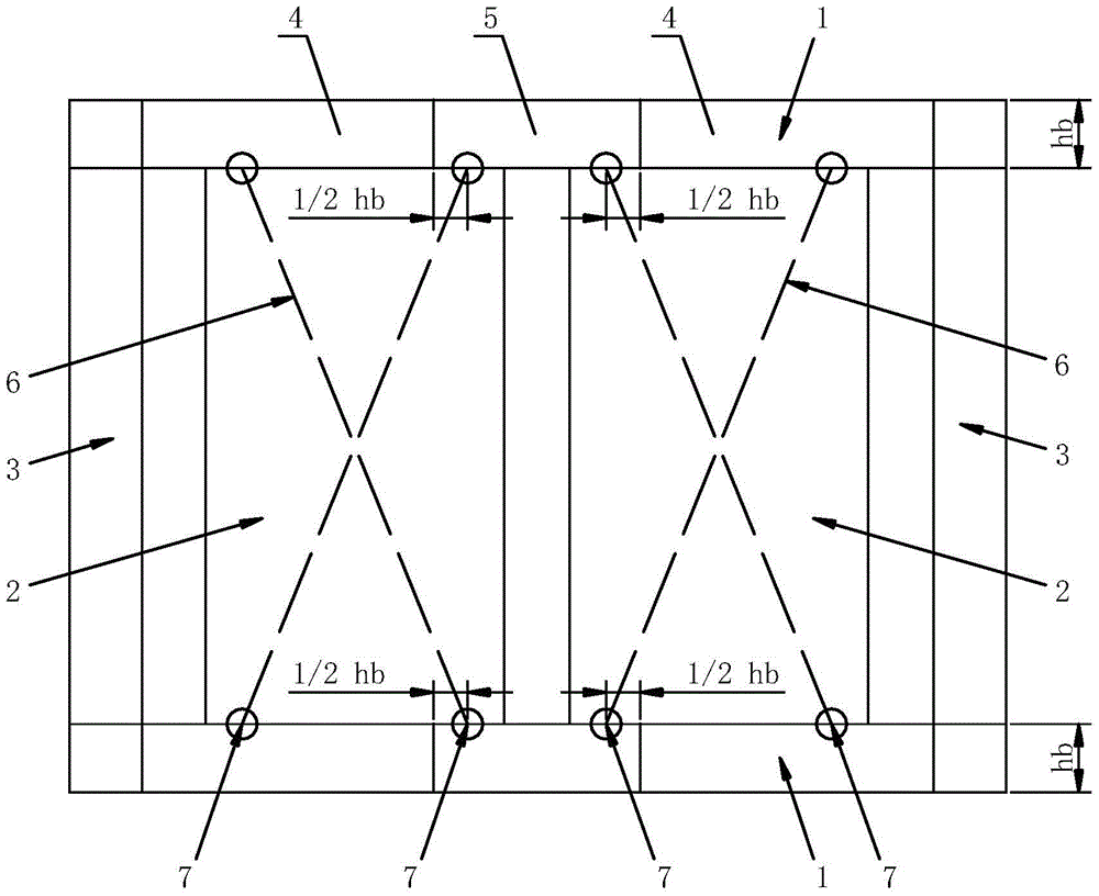
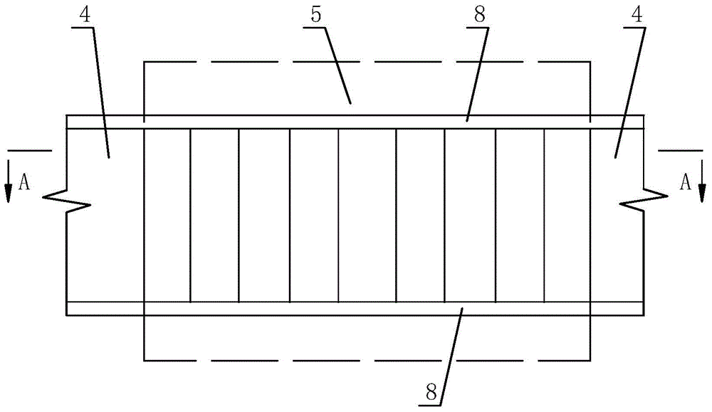
[0046] Then, if figure 2 , image 3 As shown, on both sides of the web 12 of the shear strengthening section 5, a flat steel plate 13 is welded closely to each other, and the thickness of the flat steel plate 13 is 1 / 3δ; then the corrugated steel plate is arranged on the flat steel plate 13 The outer side of the corrugated steel plate, the actual thickness of the corrugated steel plate is 1 / 6δ (in a word, the actual thickness of the corrugated steel plate is not greater than 20mm), so that the first horizontal section 9 of the corrugated steel plate is welded close to the flat steel plate 13, so that The oblique section 10 of the corrugated steel plate is welded to the two flanges 8 of the shear strengthening section 5; and the second horizontal section 11 of the corrugated steel plate is located inside the flange 8 of the shear strength...

Embodiment 2

[0048] According to the requirement of shear bearing capacity, the required thickness δ of the corrugated steel plate is not greater than 20mm.

[0049] Then, the actual thickness of the corrugated steel plate is the required thickness δ; figure 2, Figure 4 As shown, the corrugated steel plate is arranged on both sides of the web 12 of the shear strengthening section 5, and at the point 7 of the vertical resultant force, the first horizontal section 9 of the corrugated steel plate is close to the The web 12 of the steel beam 1 is welded; the oblique section 10 of the corrugated steel plate is welded to the two flanges 8 of the shear reinforcement section 5; and the second horizontal section 11 of the corrugated steel plate is located at the The inside of the flange 8 of the shear reinforcement section 5 is welded with the second horizontal section 11 and the two flanges 8 of the shear reinforcement section 5 .

[0050] The shear strengthening structure of steel girders of ...


PUM

PropertyMeasurementUnit
thicknessaaaaaaaaaa

Abstract

The invention provides a shear-resisting reinforced structure of steel girders, including buckling-resistant steel plate walls and steel girders at the upper and lower ends thereof, the steel girders are H-shaped or I-shaped steel girders, and the equivalent eccentric cross bracing of the buckling-resistant steel plate walls is connected with steel girders. The beams intersect at the point where the vertical resultant force acts; the steel beam includes a shear-reinforced section and a non-shear-reinforced section, take the beam height of the steel beam as hb, and the shear-reinforced section includes the vertical resultant force corresponding to two adjacent buckling-resistant steel plate walls The area between the action points and the area where the vertical force action point extends outward for 1 / 2hb; corrugated steel plates are provided on both sides of the web plate of the shear reinforcement section, and the corrugated steel plates include the first horizontal section, the second horizontal section and the oblique Section, at the point where the vertical resultant force acts, the first horizontal section is welded close to the web of the steel beam; the oblique section is welded to the two flanges of the shear-reinforced section. The invention improves the shear bearing capacity of the steel girder without increasing the height of the web to affect the building function, and at the same time avoids the problems of procurement and welding caused by the use of thick plates or variable-height beams for the steel girder.

Description

technical field [0001] The invention relates to the technical field of construction engineering, in particular to a shear-resistance strengthening structure of steel beams. Background technique [0002] As a structural energy-dissipating member with excellent performance, the buckling-resistant steel plate wall has very stable hysteretic characteristics and good low-cycle fatigue characteristics, which can greatly improve the lateral stiffness and bearing capacity of the structure, and at the same time provide the structure with plastic energy dissipation. It provides a considerable additional damping ratio, thereby reducing the seismic response of the structure, so it has a wide application prospect. [0003] In order to avoid the adverse effects of additional axial force and additional bending moment on the surrounding columns after the steel plate wall is connected to the surrounding columns, the buckling-resistant steel plate wall is generally connected on both sides, th...

Claims


Application Information

Patent Timeline
Patent Type & Authority Patents(China)
IPC IPC(8): E04C3/04E04B1/98E04G23/02
Inventor 孙飞飞李国强金华建
Owner TONGJI UNIV
Why Eureka
Try Eureka