Automobile oil cooler

A technology for oil coolers and automobiles, used in engine components, engine lubrication, lubricating parts, etc., can solve the problems of high production cost, complex structure, limited contact area of ​​oil cooler tubes, etc., and slow down the oil flow speed. , good oil cooling effect, the effect of reducing production cost

Inactive Publication Date: 2017-02-22
RUIAN XINHAI AUTO PARTS
View PDF11 Cites 1 Cited by
  • Summary
  • Abstract
  • Description
  • Claims
  • Application Information

AI Technical Summary

Problems solved by technology

The automotive oil cooler with the above structure requires the setting of metal spoilers, which has a complicated structure and high production cost, and the contact area between the inner hole and the outer wall of the oil cooler tube body and the cooling water is limited, and the cooling area cannot be further increased, so it cannot For better oil cooling

Method used


Image

  • Automobile oil cooler
  • Automobile oil cooler

Examples


Embodiment Construction

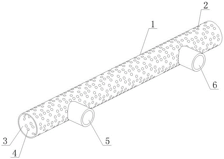
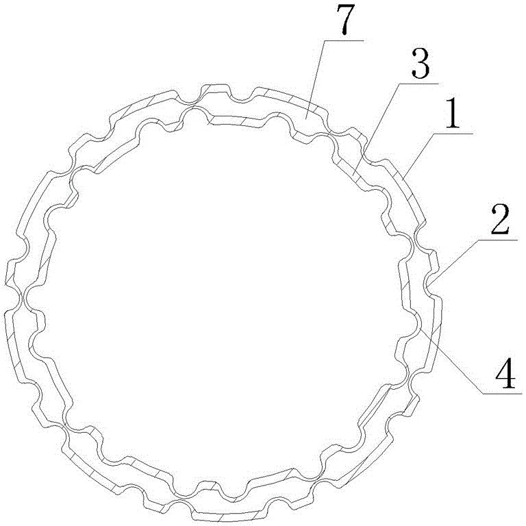
[0012] As shown in the figure, the automotive oil cooler of the present invention includes an oil cooler tube body, the oil cooler tube body has a double-layer tube wall with an inner tube wall 3 and an outer tube wall 1, and the tubes with inner and outer double-layer tube walls The end is sealed and closed, and the middle of the inner and outer double-layer pipe walls surrounds an oil passage cavity 7. One end of the outer pipe wall 1 is provided with an oil inlet 5 and the other end is provided with an oil outlet 6, and the oil inlet and outlet are connected to the oil passage. Cavity 7, the outer tube wall 1 is densely covered with irregularly distributed first concave points 2, the first concave points 2 are formed on the outer tube wall 1 by rolling, and the inner tube wall 3 is densely covered with irregular Distributed second concave points 4, the second concave points 4 are formed on the inner tube wall 3 by rolling, the first and second concave points are aligned with...


PUM


Abstract

The invention discloses an automobile oil cooler. The automobile oil cooler comprises an oil cooler pipe body, wherein the oil cooler pipe body has inner and outer layer pipe walls; the pipe ends of the inner and outer layer pipe walls are sealed; an oil passing cavity is defined between the inner and outer layer pipe walls; an oil inlet is formed in one end of the outer layer pipe wall, and an oil outlet is formed in the other end of the outer layer pipe wall; and the oil inlet and the oil outlet communicate with the oil passing cavity. The automobile oil cooler is characterized in that irregularly distributed first pits are densely arranged on the outer layer pipe wall; irregularly distributed second pits are densely arranged on the inner layer pipe wall; some of the first pits and the second pits align to each other, and some of the first pits and the second pits are staggered; and the depth of the first pits and the second pits is equal to a half of the distance between the inner layer pipe wall and the outer layer pipe wall. According to the automobile oil cooler, the structure is simple, the cooling area is increased, a better engine oil cooling effect can be achieved, and the production cost is effectively reduced.

Description

technical field [0001] The invention relates to an automobile oil cooler used for cooling automobile engine oil. Background technique [0002] The automobile oil cooler is used for the cooling of automobile engine oil. The automobile oil cooler in the prior art includes an oil cooler pipe body. The oil cooler pipe body has inner and outer double-layer pipe walls. The middle of the double-layer pipe wall encloses an oil passage cavity. One end of the outer pipe wall of the oil cooler pipe is provided with an oil inlet and the other end is provided with an oil outlet. The oil inlet and outlet are evenly connected to the oil passage cavity. A metal spoiler is installed in the cavity, and the structure of the metal spoiler is to punch out a small window on a metal sheet. The function of the metal spoiler is to slow down the flow speed of the oil so that the oil can get better heat exchange in the oil cooler tube. Fully cooled, the inner hole and outer wall of the oil cooler tub...

Claims


Application Information

Patent Timeline
IPC IPC(8): F16N39/02
CPCF16N39/02
Inventor 余席枝
Owner RUIAN XINHAI AUTO PARTS
Why Eureka
Try Eureka