Gate drive circuit

A technology of gate drive circuit and gate, which is applied in the direction of digital memory information, instruments, static memory, etc., and can solve the problem of single scanning mode of gate drive circuit

Active Publication Date: 2015-09-02
SHENZHEN CHINA STAR OPTOELECTRONICS TECH CO LTD
View PDF6 Cites 31 Cited by
  • Summary
  • Abstract
  • Description
  • Claims
  • Application Information

AI Technical Summary

Problems solved by technology

[0006] The scanning mode of the existing gate drive circuit is usually relatively simple, and often can only perform forward scanning or reverse scanning at the same time, and can only perform progressive scanning or interlaced scanning at the same time. Improve the gate drive circuit to realize the diversification of gate scanning methods to meet the needs of different display products

Method used


Image

  • Gate drive circuit
  • Gate drive circuit
  • Gate drive circuit

Examples


Embodiment Construction

[0063] In order to further illustrate the technical means adopted by the present invention and its effects, the following describes in detail in conjunction with preferred embodiments of the present invention and accompanying drawings.

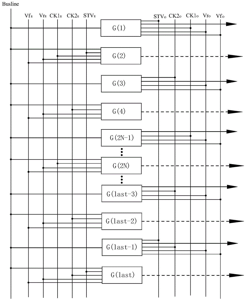
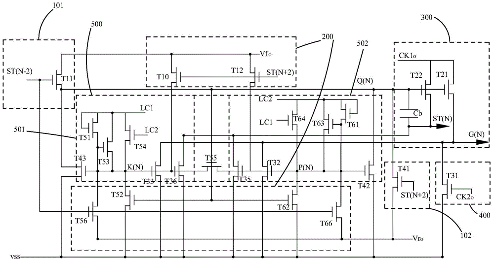
[0064] Please also see Figure 1 to Figure 3 , the present invention provides a gate driving circuit. Such as figure 1 As shown, the gate drive circuit of the present invention includes:

[0065] A plurality of GOA unit circuits, wherein each odd-numbered GOA unit circuit is cascaded, and each even-numbered GOA unit circuit is cascaded;

[0066] Corresponding to the odd-numbered-level GOA unit circuits, they are respectively used to provide the odd-numbered first scan control signal Vf O , Odd-level second scan control signal Vr O , Odd-level scan start signal STV O , Odd-level first high-frequency clock signal CK1 O , Odd-level second high-frequency clock signal CK2 O the signal line;

[0067] Corresponding to the even-numbered-level ...


PUM


Abstract

The invention provides a gate drive circuit. Each odd-level GOA unit circuit is cascaded, and each even-level GOA unit circuit is cascaded. An odd-level first scanning control signal and an odd-level second scanning control signal (VfO, VrO), an odd-level scanning starting signal (STVO), an odd-level first high-frequency clock signal, and an odd-level second high-frequency clock signal (CK1O, CK2O) are arranged corresponding to the odd-level GOA unit circuit. An even-level first scanning control signal and an even-level second scanning control signal (VfE, VrE), an even-level scanning starting signal (STVE), an even-level first high-frequency clock signal, and an even-level second high-frequency clock signal (CK1E, CK2E) are arranged corresponding to the even-level GOA unit circuit. Through controlling potential of the odd-level first scanning control signal and the odd-level second scanning control signal (VfO, VrO), and potential of the even-level first scanning control signal and the even-level second scanning control signal (VfE, VrE), cooperating with the odd-level scanning starting signal (STVO) and the even-level scanning starting signal (STVE) in different time sequence, the odd-level GOA unit circuits and the even-level GOA unit circuits can be controlled to perform forward scanning or backward scanning at the same time or at different time.

Description

technical field [0001] The invention relates to the field of liquid crystal display, in particular to a grid driving circuit. Background technique [0002] A Liquid Crystal Display (LCD) has many advantages such as a thin body, power saving, and no radiation, and has been widely used. Such as: LCD TV, mobile phone, personal digital assistant (PDA), digital camera, computer screen or notebook computer screen, etc., occupy a dominant position in the field of flat panel display. [0003] Most of the liquid crystal displays currently on the market are backlight liquid crystal displays, which include a liquid crystal display panel and a backlight module. The working principle of the liquid crystal display panel is to pour liquid crystal molecules between the thin film transistor array substrate (Thin Film Transistor Array Substrate, TFT Array Substrate) and the color filter substrate (Color Filter, CF), and apply driving force on the two substrates. The voltage is used to contr...

Claims


Application Information

Patent Timeline
Patent Type & Authority Applications(China)
IPC IPC(8): G09G3/36
CPCG09G3/3677G09G2310/0286G09G3/3648G09G3/3696G09G2310/0221G09G2310/0283G11C19/28
Inventor 曹尚操
Owner SHENZHEN CHINA STAR OPTOELECTRONICS TECH CO LTD
Why Eureka
Try Eureka