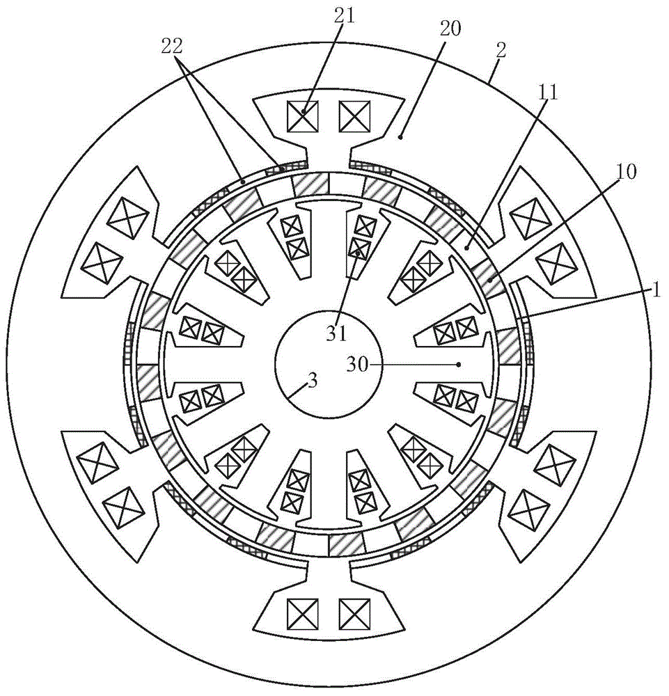
Double-stator magnetic field modulation permanent magnet motor

A magnetic field modulation and permanent magnet motor technology, which is applied in the direction of motors, electromechanical devices, electric vehicles, etc., can solve the problems of difficult heat dissipation of permanent magnets, difficulty in installing permanent magnets, and increased manufacturing costs, and achieves simple structure, reduced weight, and improved efficiency effect

Active Publication Date: 2015-09-02
JIANGSU UNIV
View PDF4 Cites 30 Cited by
  • Summary
  • Abstract
  • Description
  • Claims
  • Application Information

AI Technical Summary

Problems solved by technology

This structure has the following disadvantages: First, because the permanent magnets are placed on the rotor, the installation of the permanent magnets is difficult, especially in high-speed motion occasions, the structural reliability is poor, and the permanent magnets have the risk of falling off; secondly, the permanent magnets are placed in the double stator When it is on the rotor between the permanent magnets, it is not easy to dissipate heat, and there is a risk of high temperature demagnetization
In order to improve the power density of this type of motor and enhance the power distribution performance of the motor, it can be directly designed as a double-stator structure. However, in the stator permanent magnet motor with a traditional double-stator structure, the amount of permanent magnets will be doubled, which will undoubtedly increase. High manufacturing cost; secondly, the height of the teeth of the rotor and the height of the magnetic yoke are also approximately twice that of the unilateral motor; therefore, this type of motor has a large moment of inertia, large volume, large iron loss, low power density, and low efficiency. Low, high manufacturing cost

Method used


Image

  • Double-stator magnetic field modulation permanent magnet motor

Examples


Embodiment Construction

[0025] The following will clearly and completely describe the technical solutions in the embodiments of the present invention with reference to the drawings in the embodiments of the present invention.

[0026] In describing the present invention, it should be understood that the terms "center", "longitudinal", "transverse", "upper", "lower", "front", "rear", "left", "right", " The orientations or positional relationships indicated by "vertical", "horizontal", "top", "bottom", "inner" and "outer" are based on the orientations or positional relationships shown in the drawings, and are only for the convenience of describing the present invention and Simplified descriptions, rather than indicating or implying that the device or element referred to must have a particular orientation, be constructed and operate in a particular orientation, and thus should not be construed as limiting the invention. In addition, the terms "first" and "second" are used for descriptive purposes only, ...


PUM


Abstract

The invention discloses a double-stator magnetic field modulation permanent magnet motor comprising an inner stator, an outer stator, and a rotor. Air gaps are formed between the rotor and the inner and outer stators. The rotor is formed by magnetic conductors and non-magnetic conductors which are arranged alternately. The outer stator is formed by outer stator teeth, radial magnetizing permanent magnets, and an armature winding. The radial magnetizing permanent magnets adhere to the inner surfaces of the outer stator teeth. Adjacent permanent magnets on the same outer stator tooth have opposite magnetizing directions. The inner stator is just formed by inner stator teeth equipped with grooves along the circumferential direction and an armature winding in the grooves while not being provided with any permanent magnet. According to the double-stator magnetic field modulation permanent magnet motor, the two armature windings are used while the amount of the permanent magnets is not increased. Thus, an armature magnetic field is fully utilized and a power factor and the power density are increased. Compared with a product in the prior art, the double-stator magnetic field modulation permanent magnet motor is not provided with a rotor magnetic conductive yoke portion, decreased in rotor size and iron loss, and increased in the power density and efficiency, and can be used in power systems such as electric automobile, wind power generation or the like.

Description

technical field [0001] The invention relates to a double-stator magnetic field modulation type permanent magnet motor, which can be used in technical fields such as electric vehicles, wind power generation, and ship drive. Background technique [0002] With the continuous development of industrial technology, permanent magnet motors have been widely used in electric vehicles, wind power generation, ship drives and other fields. In high-power drive and power generation systems, the volume of the motor is large. In order to increase the power density of the motor, enhance the power distribution capability of the system, and reduce costs, the motor can adopt a double-stator structure. Since the permanent magnets and armature windings of the traditional permanent magnet synchronous motor are placed on the stator side or the rotor side respectively, when a double stator structure is adopted, the permanent magnets are generally placed on the rotor side, and the rotor is located in...

Claims


Application Information

Patent Timeline
Patent Type & Authority Applications(China)
IPC IPC(8): H02K16/04H02K1/16H02K1/17H02K1/22
CPCY02T10/64
Inventor 杜怿邹春花叶洋滔周爱琪肖凤诸言
Owner JIANGSU UNIV
Why Eureka
Try Eureka