Telescopic shifting finger protecting cover structure for spiral pushing and conveying device and mounting mode

A technology of auger and installation method, which is applied in application, threshing equipment, packaging, etc., and can solve problems such as vibration and energy loss

Inactive Publication Date: 2015-09-09
XIHUA UNIV
View PDF0 Cites 0 Cited by
  • Summary
  • Abstract
  • Description
  • Claims
  • Application Information

AI Technical Summary

Problems solved by technology

Among them, the structure of the finger guard is as follows: figure 2 As shown, in addition to linear sliding, that is, telescopic movement, the dial finger relative to the finger guard will also produce a relatively large lateral swing. In the process of swinging back and forth, due to the rapid reversal, the lateral movement of the dial finger will have a large impact. Instantaneous acceleration will inevitably cause a strong impact between the finger and the sheath, causing vibration, continuous collision and friction between the finger and the sheath, resulting in unnecessary energy loss
[0004] In the domestic patent literature search, no patent literature reports related to the technology of the present invention have been found, so it is necessary to improve this

Method used


Image

  • Telescopic shifting finger protecting cover structure for spiral pushing and conveying device and mounting mode
  • Telescopic shifting finger protecting cover structure for spiral pushing and conveying device and mounting mode
  • Telescopic shifting finger protecting cover structure for spiral pushing and conveying device and mounting mode

Examples


Embodiment Construction

[0017] The present invention will be further described below in conjunction with the accompanying drawings.

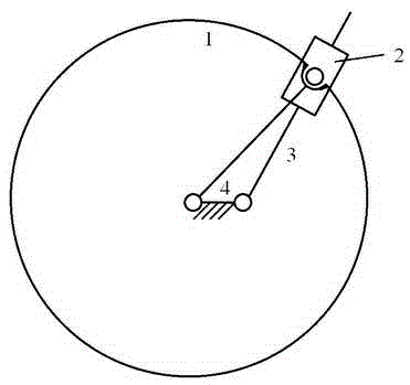
[0018] image 3 It is a schematic diagram of the mechanism movement of the new telescopic finger movement mechanism. No. 1 is the conveying roller, which rotates clockwise and is the active part of the mechanism. No. 2 is the newly added turning block, which can perform rotational movement relative to 1. No. 3 is the telescopic dial Refers to the reciprocating movement relative to the rotary block 2, which is shown as extending and retracting to the drum, and at the same time rotates clockwise with the drum 1 to realize the feeding action, which is the functional executive part of this mechanism. Number 4 is a frame, which is relatively stationary and is used to install the rotary joint of the drum and the finger.

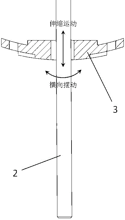
[0019] Figure 4 In the schematic diagram of the installation structure of the rotary block, the rotation between the rotary block and the telescopic fin...


PUM


Abstract

The invention provides a telescopic shifting finger protecting cover structure for a spiral pushing and conveying device and a mounting mode. The telescopic shifting finger and protecting finger cover structure is that a telescopic shifting finger can be telescoped and fed on a conveying roller of a cutting platform of a harvesting machine through a complete single-degree-of-degree connecting mechanism; a telescopic shifting finger cover is formed by combining an inner cover and an outer cover and is fixedly mounted on the roller; a rotating block is arranged in the telescopic shifting finger cover and oscillated by a reciprocating manner, wherein the rotating block sleeves a shifting finger rod; the shifting finger rod can telescopically slide in the rotating block; the telescopic shifting finger cover, the telescopic shifting finger and the rotating block are mounted in the roller of the cutting platform of the harvesting machine.

Description

technical field [0001] The invention relates to a structure and installation method of a telescopic finger protector for an auger, in particular to a novel telescopic finger movement mechanism and an installation structure of a header drum of an agricultural full-feed combine harvester. It belongs to the technical field of agricultural machinery manufacturing. Background technique [0002] The operation process of a typical full-feed rice and wheat harvesting machine is: cutting, conveying, threshing, cleaning, and siloing. The auger is a material conveying device widely used in rice and wheat harvesting machinery. Its main function is to transport the ears of rice and wheat cut off by the harvesting mechanical header to the threshing and cleaning device, and the transport process must be smooth and not blocked. The conveying work of the auger is divided into two aspects. On the one hand, when the drum rotates, the continuous left-handed or right-handed helical blades arra...

Claims


Application Information

Patent Timeline
IPC IPC(8): A01D57/26A01F17/02
Inventor 陈华王强王霜廖敏梁剑孙书民
Owner XIHUA UNIV
Why Eureka
Try Eureka