
Load pressure divider

A technology of voltage divider and heavy objects, which is applied in the direction of appliances that help people walk, medical science, and prostheses. It can solve the problems of unreachable, unrelieved burden, and user injury, so as to save physical strength, reduce weight pressure, The effect of improving work efficiency

Inactive Publication Date: 2015-09-09
LUOYANG INST OF SCI & TECH
View PDF6 Cites 4 Cited by
  • Summary
  • Abstract
  • Description
  • Claims
  • Application Information

AI Technical Summary

Problems solved by technology

[0002] Most of the current load-bearing and pressure-dividing equipment does not play the role of pressure-dividing, but through the design of the equipment, it is more in line with the principles of ergonomics, which improves the comfort of the backpack and makes people feel comfortable for a while. The method of comfort does not reduce people's burden in essence, so naturally it cannot talk about the effect of weight distribution
Most people's requirement is to have a device that can really reduce the burden on the body, and the products currently on the market obviously fail to meet people's requirements.
What's more, some unscrupulous merchants exaggerate their own products, which not only fail to achieve the effect of their own publicity, but also cause damage to people's cervical spine, spine, back and other parts due to unreasonable mechanical structure design. If the user uses it for a long time, it will inevitably cause different degrees of damage to the user's body

Method used


Image

  • Load pressure divider
  • Load pressure divider
  • Load pressure divider

Examples


Embodiment Construction

[0013] The present invention will be further described in detail below with reference to the accompanying drawings and specific embodiments.

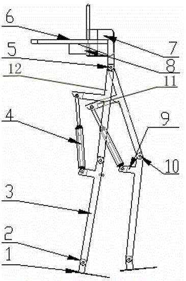
[0014] As shown in the figure, a load-bearing voltage divider includes two foot plates 1, two calf brackets 3 and two thigh brackets 12, the foot plate 1 and the calf bracket 3 are hinged through the joint I2, and the calf bracket 3 is connected to the thigh The brackets 12 are hinged through the joint II10, and a detection device for obtaining the walking information of the weight-bearing person is installed at the joint II10. The upper ends of the two thigh brackets 12 are hinged through the joint III5, and the upper ends of the two thigh brackets 11 are also provided with a support frame 8. , the upper end of the support frame 8 is provided with a heavy object tray 6 and a backrest 7; on the corresponding calf support 3 and thigh support 11, a cylinder support I9 and a cylinder support II11 are respectively provided, and a cylinder 4 ...


PUM


Abstract

A load pressure divider comprises two foot plates, two crus supports and two thigh supports. Each foot plate is hinged to the corresponding crus support via a joint I, each crus support is hinged with the corresponding thigh support via a joint II, detecting devices for acquiring walking information of a load carrying person are mounted at the positions of the joints II, the upper ends of the two thigh supports are hinged with each other via a joint III, a support frame is arranged at the upper ends of the thigh supports, a weight carrying tray and a backrest are arranged at the upper end of the support frame, an air cylinder support I and an air cylinder support II are arranged on each of the crus supports and the corresponding thigh support respectively, an air cylinder is connected between each of the air cylinder supports I and the corresponding air cylinder support II, and an electromagnetic valve and a controller are arranged between each of the air cylinder supports I and the corresponding air cylinder support II. The load pressure divider has the advantages that load pressure can be lowered, physical power of the load carrying person can be saved, and working efficiency of tourists or other people needing to carry loads is improved.

Description

technical field [0001] The present invention relates to equipment for reducing physical strength, in particular to a load-bearing voltage divider. Background technique [0002] Most of the current load-bearing partial pressure equipment does not play the role of partial pressure, but through the design of the equipment, it is more ergonomic, which improves the comfort of the backpack and makes people feel comfortable for a while. The method of comfort does not reduce people's burden in essence, and naturally it can't talk about the effect of partial pressure. However, most people's requirements are to have a device that can really reduce the burden on the body. The products currently on the market obviously cannot meet people's requirements. What's more, some unscrupulous merchants exaggerate their products, not only can not achieve the effect of their own publicity, but also because of the unreasonable mechanical structure design, it will even cause damage to people's cerv...

Claims


Application Information

Patent Timeline
IPC IPC(8): A61H3/00A61F2/50A61F2/70
Inventor 佟红霞杨海军常云鹏王海霞杨德芹邹武
Owner LUOYANG INST OF SCI & TECH
Learn More