Clamp for processing vertical positioning surface of tail wing of airplane

A vertical stabilizer and empennage technology, which is applied in the direction of manufacturing tools, metal processing equipment, metal processing machinery parts, etc., can solve the problems of non-arbitrary adjustment, difficulty in design and manufacture, and low efficiency of manual operation, so as to achieve flexible and stable adjustment, Excellent clamping effect and good attitude adjustment effect

Active Publication Date: 2015-09-09
WENZHOU UNIVERSITY
View PDF8 Cites 17 Cited by
  • Summary
  • Abstract
  • Description
  • Claims
  • Application Information

AI Technical Summary

Problems solved by technology

[0002] In aviation, aerospace, automobile and other products, there are a large number of thin-walled parts with poor stiffness and complex curved surface shape. Traditional thin-walled parts are trimmed, drilled, and measured using special tooling. The surface of the tooling has the same Consistent curved surface shape of thin-walled parts, each set of tooling can only be applied to one kind of thin-walled parts, under the growing demand for small batches and multiple varieties in various industries, the cost is too high to meet the actual production needs
[0003] Although some existing fixtures can realize the positioning support of thin-walled curved surface parts through manual adjustment according to the shape, size and process requirements of the parts, the manual operation has low efficiency and poor precision, and it is difficult to meet the high efficiency requirements of thin-walled curved surface parts production. And most of its support and fixing units are connected by being fixed on the T-shaped groove of the workbench, so that the distance of the support and fixation unit in certain directions of the workbench is a fixed value and cannot be adjusted; Chinese Patent No. 200810056655.5 discloses the nail height adjustment unit The Y-direction distance is determined by the length of the positioning plate, and the X-direction distance is determined by the distance of the positioning hole on the base pillow. Neither direction can be adjusted arbitrarily.
[0004] At present, the fully automatic flexible tooling based on measurement, control, machinery and other disciplines developed at home and abroad uses hydraulic control to adjust the distance between the supporting and fixed units. Its complex structure, difficult design and manufacture, and high cost hinder its use in enterprises. In the face of the above problems, it is necessary to study the multi-point flexible tooling for thin-walled curved parts that are suitable for actual needs

Method used


Image

  • Clamp for processing vertical positioning surface of tail wing of airplane
  • Clamp for processing vertical positioning surface of tail wing of airplane
  • Clamp for processing vertical positioning surface of tail wing of airplane

Examples


Embodiment Construction

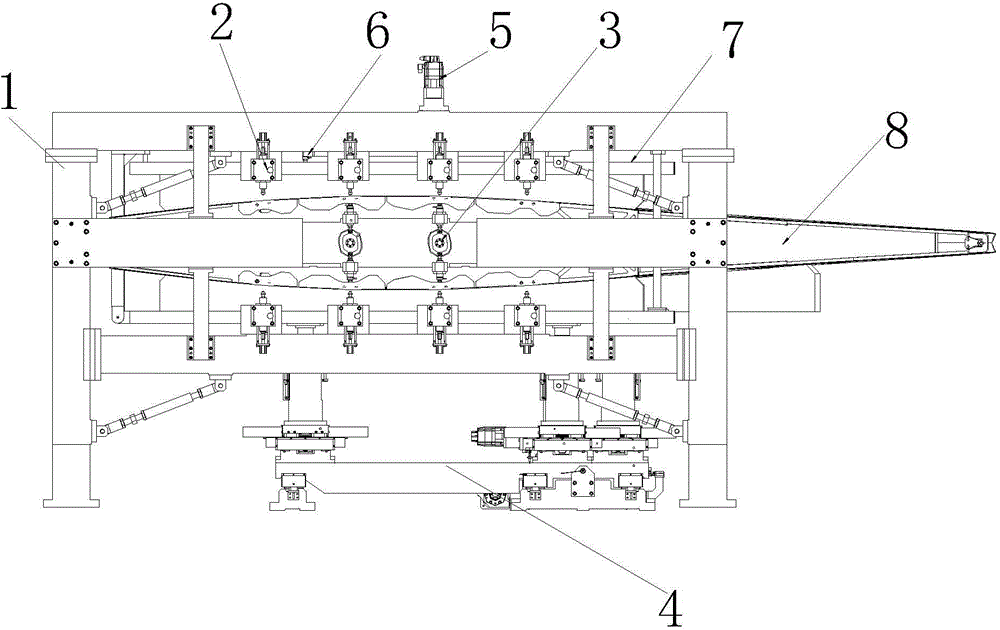
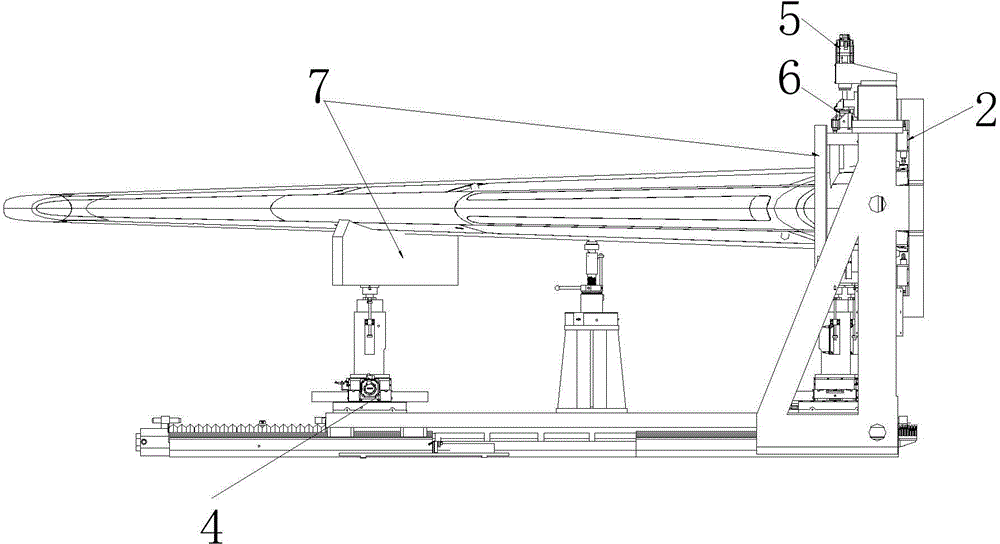
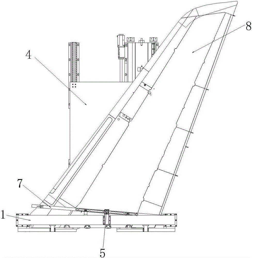
[0032] like Figure 1~3 As shown, the fixture used for processing the vertical stabilizer of the aircraft empennage includes a bracket 1 and an attitude adjustment positioning device 4 located on one side of the bracket for providing positioning support for the middle and tail of the empennage. The upper and lower beams of the bracket 1 are equipped with multiple In the external support device 2 that is pressed against the head outside of the empennage 8, a plurality of internal support devices 3 for compressing the inside of the empennage head are installed on the middle beam of the support 1, and are also installed on the support 1 for empennage Head fixed main clamping mechanism 6. The external supporting devices installed on the upper cross beam of the support are opposite to the external supporting devices installed on the lower cross beam, and the internal supporting devices installed on the middle cross beam of the support are opposite to each other.

[0033] Wherein, ...


PUM


Abstract

The invention relates to a clamp for processing a vertical positioning surface of a tail wing of an airplane. The clamp comprises a bracket, and a gesture adjusting positioning device which is positioned at one side of the bracket and used for providing positioning supporting to the medium tail part of the tail wing; external supporting devices for compressing the outer side of the head part of the tail wing are mounted on an upper cross beam and a lower cross beam of the bracket; an inner supporting device for compressing the inner side of the head part of the tail wing is mounted on a medium cross beam of the bracket; a main clamping mechanism for fixing the head part of the tail wing is also mounted on the bracket. With the adoption of the clamp, the vertical positioning surface can be automatically positioned and clamped; the requirement on positioning and assembling of large and poor-rigidity parts can be met; after gesture adjusting, the clamping effect is outstanding; the parts are free of deformation due to clamping; the adjusting efficiency is high; the adjusting is flexible and stable.

Description

technical field [0001] The invention relates to a fixture used for machining the vertical stabilizer of an aircraft empennage. Background technique [0002] In aviation, aerospace, automobile and other products, there are a large number of thin-walled parts with poor stiffness and complex curved surface shape. Traditional thin-walled parts are trimmed, drilled, and measured using special tooling. The surface of the tooling has the same With the consistent curved surface shape of thin-walled parts, each set of tooling can only be applied to one kind of thin-walled parts. Under the growing demand for small batches and multiple varieties in various industries, the cost is too high to meet the actual production needs. [0003] Although some existing fixtures can realize the positioning support of thin-walled curved surface parts through manual adjustment according to the shape, size and process requirements of the parts, the manual operation has low efficiency and poor precision...

Claims


Application Information

Patent Timeline
Patent Type & Authority Applications(China)
IPC IPC(8): B23Q3/06B23Q3/08
CPCB23Q3/065B23Q3/08
Inventor 冯爱新薛伟张华夏仲秋许兴旺李峰平吴浩张津超
Owner WENZHOU UNIVERSITY
Why Eureka
Try Eureka