Automatic loading-unloading device of machine tool

An automatic loading and unloading and machine tool technology, applied in the mechanical field, can solve problems such as inaccurate workpiece positioning, workpiece clamping deviation, and limited adjustment angle, so as to achieve accurate and stable gripping of workpieces by air grippers, stable gripping of workpieces by air grippers, Effects that are not easy to shift

Active Publication Date: 2015-09-09
台州中弈智能装备有限公司
View PDF12 Cites 6 Cited by
  • Summary
  • Abstract
  • Description
  • Claims
  • Application Information

AI Technical Summary

Problems solved by technology

[0004] However, the above-mentioned manipulator also has the following defects: 1. The stroke of the telescopic cylinder in the above-mentioned manipulator can only be fine-tuned by the cylinder clamping plate, and cannot be greatly adjusted according to production needs, and cannot meet the grasping requirements of workpieces in actual production; 2. The above-mentioned The installation positions of the two air claws in the manipulator can only be adjusted through the long holes on the above-mentioned splint, and the adjustment angle of the two air claws is limited, which cannot meet the needs of selecting the gripping angle of the workpiece in actual production; 3. The above-mentioned air claws There are V-shaped grooves on the inner sides of the three claws. When the air claw clamps the workpiece, it is positioned at four points. During the process of clamping the workpiece, the air claw is subjected to radial clamping forces in four directions on the outer peripheral wall of the workpiece. It is easy to cause inaccurate workpiece positioning and unstable clamping due to unbalanced force. Moreover, when the manipulator grasps the workpiece and moves it to the machine tool fixture, it is easy to cause deviations in the workpiece clamping and affect the processing of the workpiece.

Method used


Image

  • Automatic loading-unloading device of machine tool
  • Automatic loading-unloading device of machine tool
  • Automatic loading-unloading device of machine tool

Examples


Embodiment Construction

[0024] The following are specific embodiments of the present invention and in conjunction with the accompanying drawings, the technical solutions of the present invention are further described, but the present invention is not limited to these embodiments.

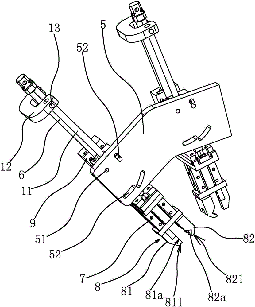
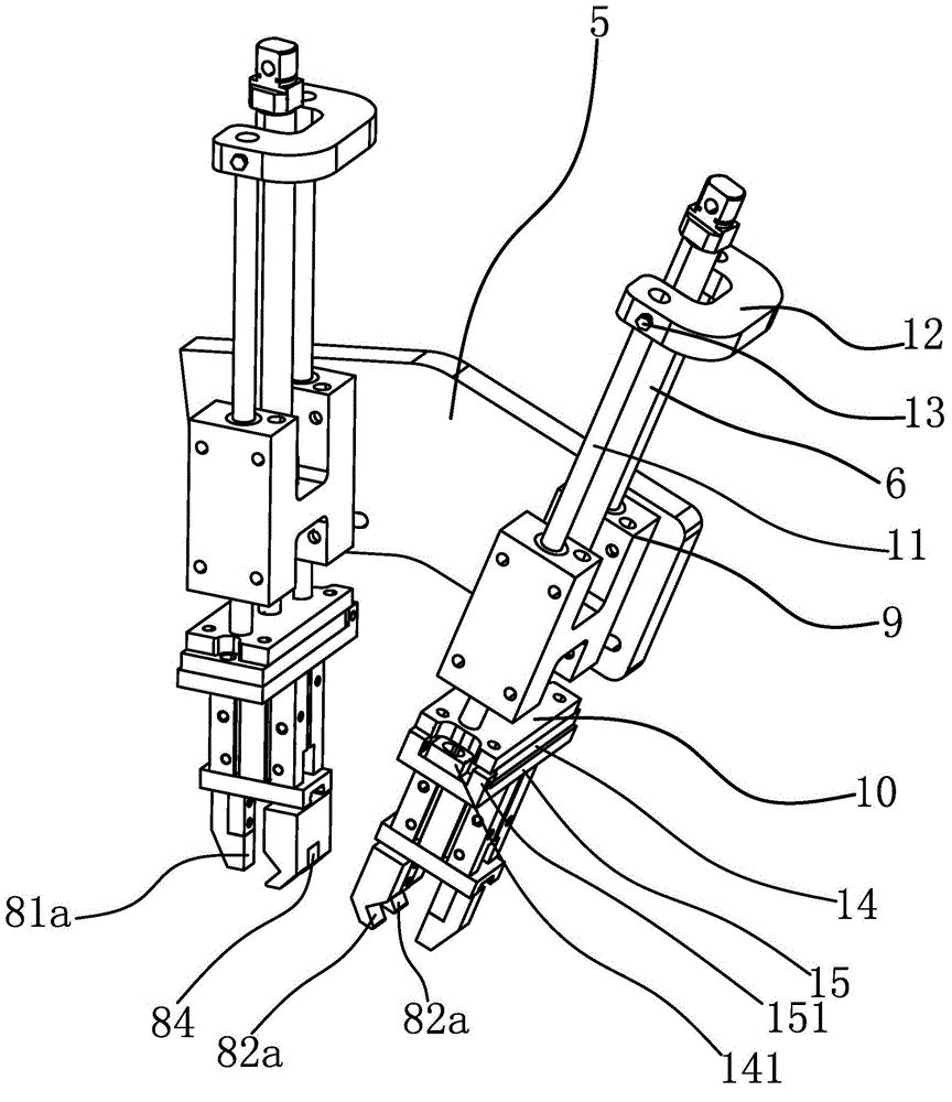
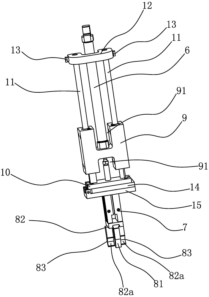
[0025] The automatic loading and unloading device of this machine tool includes installation column 1, servo motor 2, linear module 3, slider 4, connecting plate 5, hinged round hole 51, arc-shaped hole 52, telescopic cylinder 6, air claw cylinder 7, air claw 8. Claw head 1 81, clamping surface 1 81a, bottom surface 1 811, claw head 2 82, clamping surface 2 82a, bottom surface 2 821, claw toe 83, interval 84, mounting block 9, cavity 91, partition 92. Fixed plate 10, guide rod 11, limit plate 12, adjustment screw 13, angle adjustment plate 14, adjustment part 141, mounting plate 15, block 151.

[0026] Specifically, as figure 1 and Figure 4As shown, the automatic loading and unloading device includes an installation col...


PUM


Abstract

The invention provides an automatic loading-unloading device of a machine tool, and belongs to the technical field of a machine, and solves the problems for more accurately and stably grabbing a workpiece by virtue of a pneumatic claw. The automatic loading-unloading device comprises a connecting plate, a telescopic air cylinder, a pneumatic claw air cylinder and a pneumatic claw connected to the pneumatic claw air cylinder, wherein a hinge circular hole and at least one arc hole are formed in the connecting plate; the center of an arc line of each arc hole in the length direction is concentric to that of the hinge circular hole; a positioning part I is arranged in the hinge circular hole; a positioning part II is arranged in each arc hole; an installation block is positioned on the connecting plate by virtue of the positioning part I and the positioning part II; the installation block can rotate around the center of the hinge circular hole relative to the connecting plate, so that the positioning part II slides along the arc hole; the pneumatic claw comprises a claw head I and a claw head II; the inner side surface of the claw head I is provided with a flat clamping surface I; the inner side surface of the claw head II is provided with a V-shaped clamping surface II which is concaved inwards; the position of the clamping surface I corresponds to that of the clamping surface II, so that the pneumatic claw more accurately and stably grab the workpiece.

Description

technical field [0001] The invention belongs to the technical field of machinery and relates to an automatic loading and unloading device of a machine tool. Background technique [0002] When the traditional machine tool is in operation, the loading, unloading, clamping of the workpiece and the measurement of the workpiece processing size are all done manually by workers. Not only is the labor intensity of the workers high, the production efficiency is low, the machining accuracy of the workpiece is difficult to guarantee, and the scrap rate is high, but also one worker can only operate one machine, and the production cost is also high. [0003] In order to solve the above-mentioned existing problems, such as Chinese patent [application number: 201420825159.2; authorization announcement number: CN204354140U] discloses a kind of double rod concentric clamping manipulator, comprises two splints and two manipulators, described manipulator comprises fixed block, Telescopic cyli...

Claims


Application Information

Patent Timeline
Patent Type & Authority Applications(China)
IPC IPC(8): B23Q7/04
CPCB23Q7/046B23Q7/048
Inventor 金宝林
Owner 台州中弈智能装备有限公司
Why Eureka
Try Eureka