Spring clip automatic assembling machine

An automatic assembly machine and clip technology, applied in hand-held tools, manufacturing tools, etc., can solve problems such as difficulty in the compression of torsion springs, broken splints, production safety, etc., to reduce labor intensity and labor costs for workers, and ensure firm and reliable positioning , Good positioning effect

Active Publication Date: 2015-09-09
金华市晨帆饰品有限公司
View PDF8 Cites 22 Cited by
  • Summary
  • Abstract
  • Description
  • Claims
  • Application Information

AI Technical Summary

Problems solved by technology

[0003] At present, the spring clip 9 of the above-mentioned structure is manually assembled, the operation is relatively complicated, and it is difficult to master it, thus affecting the production efficiency, and the torsion spring needs to be loaded in a compressed state to ensure the clamping force of the spring clip and the compression amount of the torsion spring. It is difficult to control, it is difficult to ensure that the clamping force of each spring clip is consistent, the quality stability of the clip is poor, and it is easy to cause problems such as torsion spring protruding, hurting people, losing, and splint breaking, resulting in high scrap rate and production safety problems

Method used


Image

  • Spring clip automatic assembling machine
  • Spring clip automatic assembling machine
  • Spring clip automatic assembling machine

Examples


Embodiment Construction

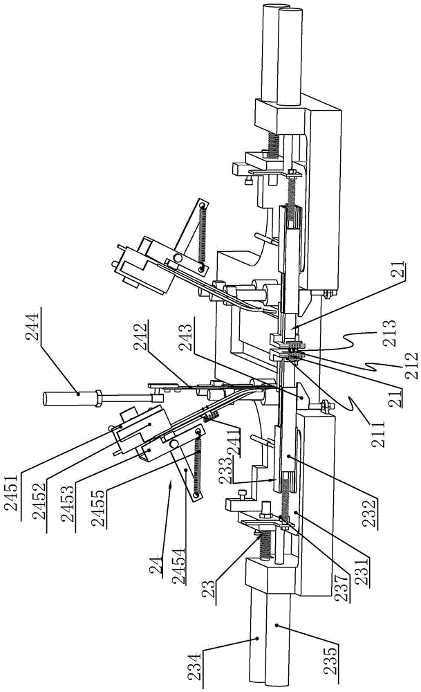
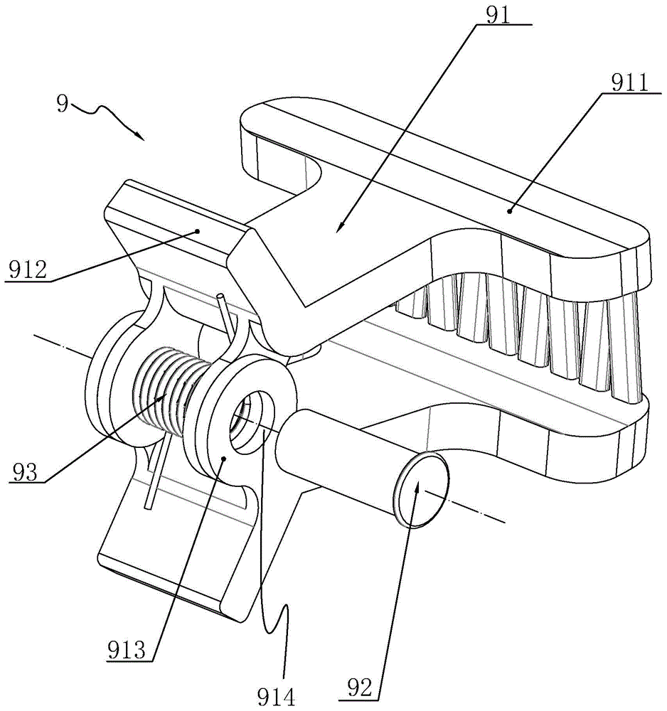
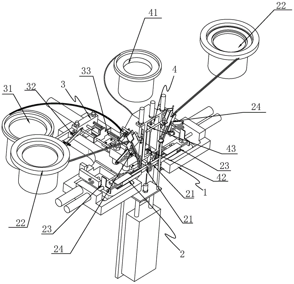
[0038] Such as Figure 2 to Figure 10 As shown, a spring clip automatic assembly machine disclosed in the present invention includes a frame 1, and the frame 1 is provided with a splint splicing device 2, a torsion spring pressing device 3 and a pin insertion device 4, and the The splint splicing device 2 includes a plywood splicing seat, and the plywood splicing seat includes two oppositely arranged splint clamping seats 21, the plywood clamping seat 21 is provided with a splint plate body positioning cavity 211 and a pivoting ear extension port 212, and the two splint clamps Between the holders 21, there are intervals between the pivoting ears 913 on the splint 91 to form a pivoting ear joint spacer cavity 213, and the pivotal ear extension port 212 communicates with the pivotal ear joint spacer cavity 213 and the splint plate body positioning cavity 211. The splint splicing seat is provided with a splint plate body positioning cavity 211 connected to the splint, the pivoti...


PUM


Abstract

The invention relates to a spring clip automatic assembling machine. The machine comprises a rack. A clamping plate splicing unit, a torsion spring compression unit and a pin insertion unit are arranged on the rack. The clamping plate splicing unit comprises a clamping plate splicing seat which comprises two opposite clamping plate clamping seats. Clamping plate body location cavities and pivoting lug stretching ports are formed in the clamping plate clamping seats. The two clamping plate clamping seats are arranged at an interval to form a pivoting lug splicing spacing cavity for a clamping plate upper pivoting lug. The pivoting lug stretching ports are communicated with the pivoting lug splicing spacing cavity and the clamping plate body location cavities. A spring clip blanking port communicated with the clamping plate body location cavities, the pivoting lug stretching ports and the pivoting lug splicing spacing cavity is formed in the clamping plate splicing seat. The pivoting lug splicing spacing cavity comprises a torsion spring feeding port in corresponding fit with the torsion spring compression unit and a pin insertion port in corresponding fit with the pin insertion unit. By means of the machine, the spring clip automatic assembly machine is provided, and the assembly efficiency and the finished product yield of spring clips are improved effectively.

Description

technical field [0001] The invention relates to an automatic equipment, in particular to an assembly machine for assembling and forming spring clips. Background technique [0002] Spring clips are common articles in people's lives, and their uses and types are also relatively wide, such as hair clips for clipping hair, book clips for holding books and paper, etc. Such as figure 1 Shown is an existing common spring clip 9, including two splints 91, a torsion spring 93 and a pin 92, the splint 91 includes a plate body and a pivot seat, the plate body includes a clamping portion 911 and a pressing portion 912, pivotally mounted It is seated at the junction of the clamping part 911 and the pressing part 912. The clamping part 911 and the pressing part 912 form a seesaw structure with the pivot mount as the fulcrum. The pivot mount is composed of two opposite pivot mount ears 913. The pivot mount ears 913 There is a pin insertion hole 914 on the top, wherein, the plate body for...

Claims


Application Information

Patent Timeline
Patent Type & Authority Applications(China)
IPC IPC(8): B25B27/02
CPCB25B27/02
Inventor 朱日贡
Owner 金华市晨帆饰品有限公司
Why Eureka
Try Eureka