
Oil press

An oil press and drive shaft technology, applied in the direction of presses, manufacturing tools, etc., can solve the problems of low oil yield, insufficient heating material, and poor extrusion material effect, so as to improve the oil yield and ensure Oil-pressing effect and balanced extrusion force

Active Publication Date: 2015-09-09
BENGBU QIONGHUAI GRAIN & OIL
View PDF5 Cites 4 Cited by
  • Summary
  • Abstract
  • Description
  • Claims
  • Application Information

AI Technical Summary

Problems solved by technology

This technical solution does not heat the material evenly, the effect of extruding the material is not good, and the oil yield is not high. This technical solution needs to be further improved.

Method used


Image

  • Oil press
  • Oil press

Examples


Embodiment Construction

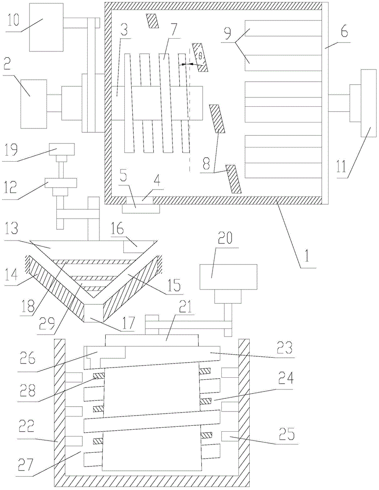
[0040] refer to figure 1 , 2 ;

[0041] An oil press provided by the present invention includes a frying part and an oil pressing part;

[0042] The frying section includes a frying box 1, a first motor 2, and a drive shaft 3. The frying box 1 is provided with a material port 4 for adding materials and discharging materials. The material port 4 is provided with a cover 5. The frying box One side of 1 is provided with a cover plate 6:

[0043] The first motor 2 is in drive connection with the transmission shaft 3, one end of the transmission shaft 3 is placed in the frying box 1, and the end of the transmission shaft 3 located in the frying box 1 is provided with a helical main stirring blade along the axial direction of the transmission shaft 3 7. The angle between the lower surface of the main stirring blade 7 and the plane perpendicular to the axial direction of the transmission shaft is θ, 5°≤θ≤10°, and the length of the main stirring blade 7 along the radial direction o...


PUM


Abstract

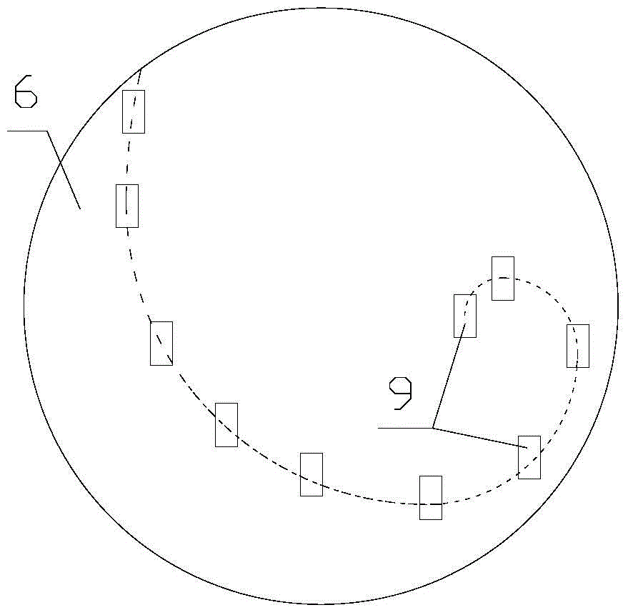
The invention discloses an oil press. The oil press comprises a frying part and an oil pressing part. The frying part comprises a frying box, a first motor and a transmission shaft, wherein a material port used for adding materials and discharging materials is formed in the frying box, a sealing cover is arranged at the material port, and a cover plate is arranged one side face of the frying box; the first motor is in transmission connection with the transmission shaft, one end of the transmission shaft is arranged in the frying box, a main spiral stirring shaft is arranged at the end, located in the frying box, of the transmission shaft in the axial direction of the transmission shaft, the included angle theta between the lower surface of the main stirring blade and the plane perpendicular to the axial direction of transmission shaft ranges from 5 degrees to 10 degrees, the length, in the radial direction of the transmission shaft, of the main stirring blade is 1.5D-2D, and D is the diameter of the transmission shaft; a plurality of auxiliary stirring blades are arranged on the inner wall of the frying box, and the auxiliary stirring blades are spirally distributed with the axial direction of the transmission shaft as the center; a plurality of material blocking plates are arranged on the cover plate, and the line connecting the centers of the material blocking plates form an Achimedean spiral; the material blocking plates extend in the axial direction of the transmission shaft. The oil press is good in oil pressing effect.

Description

technical field [0001] The invention relates to the technical field of oil press machinery, in particular to an oil press machine. Background technique [0002] The oil press refers to the machine that squeezes the oil out of the oil by increasing the temperature and activating the oil molecules with the help of external mechanical force. It can be divided into household oil presses, hydraulic oil presses, screw oil presses, new hydraulic oil presses, high-efficiency fine filter oil presses, and fully automatic oil presses. [0003] In Chinese patent application number: 201320534823.8, a household oil press is disclosed, including a wave box, a pressing chamber fixed on it, a screw is arranged in the pressing chamber, the head end of the screw rod is connected with the transmission of the wave box, and the head end of the pressing chamber is arranged There is a feed bin and a slag discharge hole at the end of the tail end. The end of the press chamber and the end of the scr...

Claims


Application Information

Patent Timeline
Patent Type & Authority Applications(China)
IPC IPC(8): B30B9/20B30B15/00
Inventor 宋代江方厚凯
Owner BENGBU QIONGHUAI GRAIN & OIL
Learn More