Transmission connector of electric bicycle

A technology for electric bicycles and transmission joints, which is applied to wheeled transmissions, rotary transmissions, vehicle components, etc., can solve problems such as personal injury, increased economic costs, trousers or skirts, chains or sprockets entangled or bitten, etc. Achieve the effect of increasing the contact area, preventing failure, and preventing loosening

Inactive Publication Date:
View PDF8 Cites 0 Cited by
  • Summary
  • Abstract
  • Description
  • Claims
  • Application Information

AI Technical Summary

Problems solved by technology

[0002] The transmission method of traditional electric bicycles adopts sprocket chain transmission. Although this transmission structure is equipped with a chain baffle, it is still an open transmission structure. The rider's trousers or skirt are easily entangled or bitten by the chain or sprocket. Even cause the rider to fall and cause property or personal injury
At the same time, as the speed increases, the chain tends to end grain or fall off after a period of use, requiring re-maintenance or installation, which brings a lot of trouble to the rider
In recent years, a transmission system in which the transmission shaft replaces the chain drive has appeared on the market, but the existing drive motor and the shaft drive need to be connected by a special hub, so special tools need to be purchased or made, which is not conducive to maintenance operations and causes economic costs increase, and at the same time, the workload of maintenance personnel is heavy during after-sales maintenance
At the same time, the traditional bicycle transmission shaft cannot be applied to the rear motor of the electric bicycle, which has brought a bottleneck to the development of the electric bicycle towards the shaft transmission.

Method used


Image

  • Transmission connector of electric bicycle
  • Transmission connector of electric bicycle
  • Transmission connector of electric bicycle

Examples


Embodiment Construction

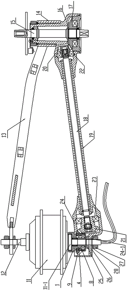
[0026] The present invention will be further described below in conjunction with the accompanying drawings.

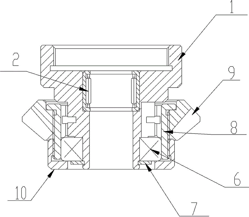
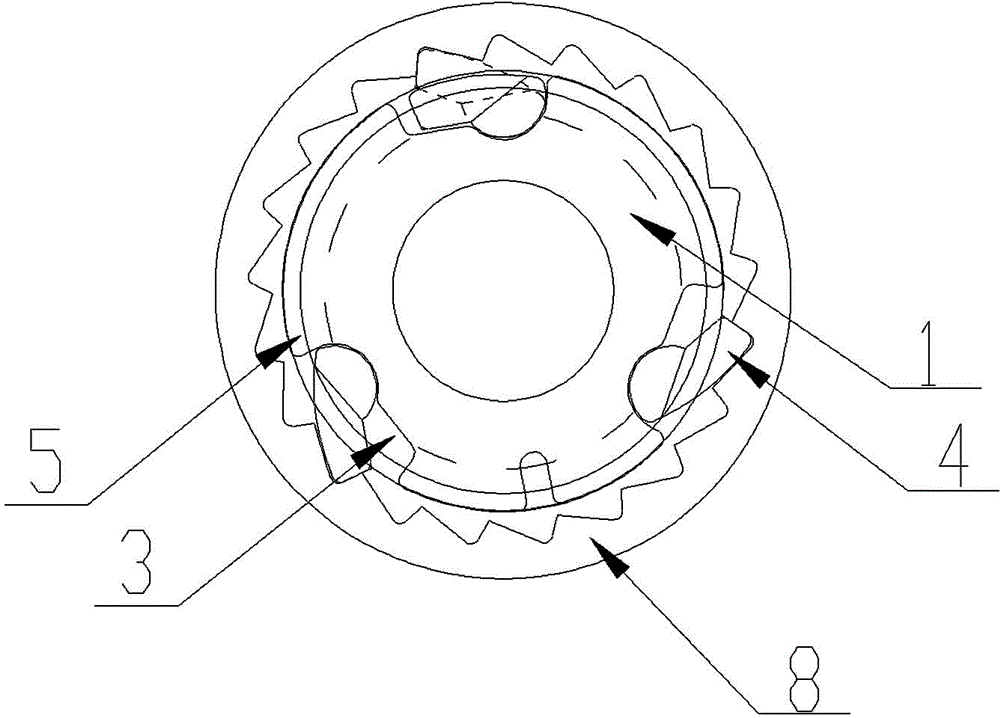
[0027] see Figure 1 to Figure 3 As shown, a transmission joint of an electric bicycle includes a connecting body 1, and the connecting body 1 is provided with at least three-stage stepped through holes. In this embodiment, the connecting body 1 is provided with three-stage stepped through holes, which is the best In the embodiment, the large-diameter section of the connecting body 1 is provided with an internal thread for connection, and the large-diameter section of the connecting body 1 is used to connect with the motor; the second stepped through hole of the connecting body 1 is provided with a The first bearing 2 installed on the support shaft of the electric bicycle is limited by the stepped through hole. The first bearing 2 adopts a needle bearing, and the connecting body 1 is slidably fitted to the electric bicycle through the first bearing 2. On the support s...


PUM


Abstract

The invention discloses a transmission connector of an electric bicycle. The transmission connector comprises a connecting body. Stepped through holes are formed inside the connecting body. The large-aperture section of the connecting body is provided with an inner thread for connecting. A first bearing is disposed in the second stepped through hole of the connecting body. A plurality of steps are disposed outside the connecting body. A plurality of pawl grooves are peripherally distributed in the middle of the outer side of the connecting body. A pawl is disposed in each pawl groove, and a pawl spring is disposed on the pawl. A ratchet is mounted on the outer lateral wall of the connecting body through a second bearing. The pawl springs, the pawls and the ratchet are matched to form a ratchet mechanism. A rear driven gear fixedly sleeves the ratchet. A fixing cover is disposed on the second bearing. The fixing cover is matched with the ratchet in a threaded manner. The transmission connector is simple in structure, high in transmission efficiency, good in stability, free of ratchet structure failure, capable of facilitating mounting connection between a drive motor and a transmission assembly, and low in cost.

Description

technical field [0001] The invention relates to bicycles, in particular to a transmission joint of an electric bicycle. Background technique [0002] The transmission method of traditional electric bicycles adopts sprocket chain transmission. Although this transmission structure is provided with a chain baffle, it is still an open transmission structure, and the rider's trousers or skirts are easily entangled or bitten by the chain or sprocket. Even cause the rider to fall and cause property or personal injury. At the same time, due to the increased speed, the chain is prone to telomeres or fall off after a period of use, requiring re-maintenance or installation, which brings a lot of trouble to the rider. In recent years, there has been a transmission system in the market in which the transmission shaft replaces the chain transmission, but the existing drive motor and the shaft transmission need to be connected by a special hub, so it is necessary to purchase or make speci...

Claims


Application Information

Patent Timeline
Patent Type & Authority Applications(China)
IPC IPC(8): B62M6/60B62M11/00B62M17/00
CPCB62M11/00B62M17/00F16D41/30
Inventor 宋兴辉
Why Eureka
Try Eureka