Manual grouting layer method pile toe three-dimensional post-pressure grouting structure and pouring method

A technology of grouting layer and pile end, which is applied in the direction of foundation structure engineering, building, sheet pile wall, etc., can solve the problems of small amount of grouting, small number of grouting holes, and the grouting pipe is easily wrapped by concrete, etc., to achieve Good material availability

Active Publication Date: 2015-09-09
BGI ENG CONSULTANTS
View PDF7 Cites 6 Cited by
  • Summary
  • Abstract
  • Description
  • Claims
  • Application Information

AI Technical Summary

Problems solved by technology

[0002] The post-grouting technology of the existing foundation pile pile end is: the pile end grouting pipe adopts a welded steel pipe (pile bottom grouting valve) with a one-way valve and a grouting hole, the length is 30-50 cm, and the bottom position extends out of the cast-in-place pile. The main reinforcement at the pile end is 10-30cm, and it is lowered into the bottom of the pile hole with the reinforcement cage and pierced into the bearing layer of the pile end by the self-weight of the reinforcement cage, and the grouting pipe is self-protected by the ground. This method has the following problems: (1) The process of lowering the reinforcement cage The exposed grouting pipe is easy to collide with hard objects such as pebbles and gravels in the hole wall, and damage the grouting pipe; (2) When the grouting pipe penetrates into the bearing layer at the pile end (such as hard soil layers such as large-sized pebbles and gravels) , it is easy to damage the grouting pipe. When the pile end is a rock formation, the grouting pipe protruding from the steel cage cannot penetrate the rock formation at all; (3) Since the pile end grouting pipe is too close to the pile concrete, the upper part It has been buried in the concrete at the pile end, so during the pouring of the pile body concrete, the grouting pipe is likely to be wrapped by the concrete, and the grouting hole is likely to be blocked later, so there is basically no choice for the time point of the post-grouting. Grouting must be done within 2-3 days after the pile concrete is poured (that is, before the strength of the pile concrete increases); (4) The grouting pipe can only be grouted in spots, and the grouting pipe is short and the number of grouting holes is limited. Once several grouting holes are blocked, the amount of grouting for the whole pile will not be large

Method used


Image

  • Manual grouting layer method pile toe three-dimensional post-pressure grouting structure and pouring method
  • Manual grouting layer method pile toe three-dimensional post-pressure grouting structure and pouring method
  • Manual grouting layer method pile toe three-dimensional post-pressure grouting structure and pouring method

Examples


Embodiment 1

[0035] The present invention also includes a pouring method for the three-dimensional rear grouting structure at the pile end by the artificial grouting layer method, which includes the following methods,

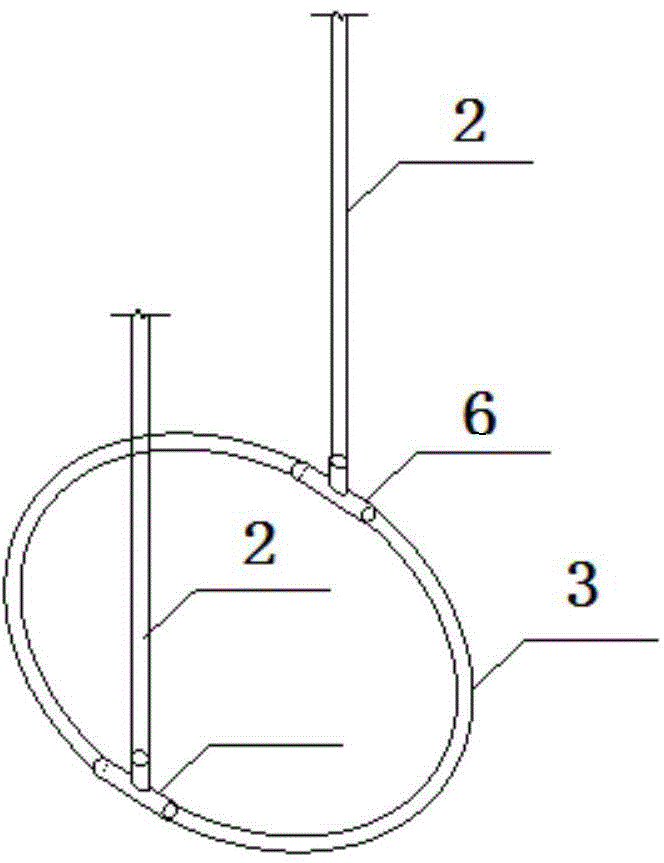
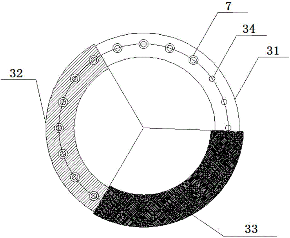
[0036]Prepare the annular grouting pipe, set a grout hole on the circular PVC steel wire pipe, press a thumbtack on the grout hole, wrap the car rubber inner tube outside, and wrap one or two layers of packing tape on the outside of the car rubber inner tube; The PVC steel wire pipe communicates with the grouting conduit through a communication valve. The rubber inner tube of the car is an ordinary bicycle inner tube.

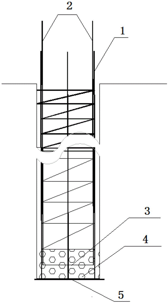
[0037] Bind the annular grouting pipe to the inner side of the main reinforcement of the reinforcement cage at a height of 20-30cm from the bottom of the cast-in-place pile;

[0038] After the annular grouting pipe is lowered to the design elevation along with the steel cage, first pour one or two trolleys of crushed stone or the amount of crushed stone tha...


PUM


Abstract

The invention relates to a manual grouting layer method pile toe three-dimensional post-pressure grouting structure, which comprises a reinforcement cage and a grouting guide pipe; the grouting guide pipe is bound to the inner side of the reinforcement cage in a parallel manner; the reinforcement cage is positioned in a pile hole of a grouting pile; the manual grouting layer method pile toe three-dimensional post-pressure grouting structure also comprises an annular grouting pipe; the annular grouting pipe is bound to the inner side of the lower part of the reinforcement cage; the elevation of the annular grouting pipe is 20-30 cm higher than the bottom elevation of the reinforcement cage; the annular grouting pipe is communicated with the grouting guide pipe; the bottom of the pile hole of the grouting pile is provided with a rubble layer with the height being 30-50 cm. When the reinforcement cage is lifted and released, collision between the reinforcement cage and things such as the construction site, soil bodies on the side wall of the pile hole and gravel-cobble at the bottom of the pile hole can be effectively avoided, so that the annular grouting pipe is protected from damage; the annular grouting pipe is wrapped in the rubble layer before grouting, and is not in contact with pile concrete, so that the problem that the annular grouting pipe is plugged due to the fact that the pile concrete wraps the annular grouting pipe is effectively solved, and the goals of curing sediment and improving the bearing capability of a pile toe are achieved through performing solidification and cementation under the effect of high-pressure cement paste.

Description

technical field [0001] The invention relates to a three-dimensional post-grouting structure and method of pile ends by artificial grouting layer method, and belongs to the field of post-grouting construction structures and techniques of pile ends of foundation piles. Background technique [0002] The post-grouting technology of the existing foundation pile pile end is: the pile end grouting pipe adopts a welded steel pipe (pile bottom grouting valve) with a one-way valve and a grouting hole, the length is 30-50 cm, and the bottom position extends out of the cast-in-place pile. The main reinforcement at the pile end is 10-30cm, and it is lowered into the bottom of the pile hole with the reinforcement cage and pierced into the bearing layer of the pile end by the self-weight of the reinforcement cage, and the grouting pipe is self-protected by the ground. This method has the following problems: (1) The process of lowering the reinforcement cage The exposed grouting pipe is eas...

Claims


Application Information

Patent Timeline
Patent Type & Authority Applications(China)
IPC IPC(8): E02D15/04E02D5/44
Inventor 吴民利周子舟冯红超杨素春王坚张略郭义先赵晓峰
Owner BGI ENG CONSULTANTS
Why Eureka
Try Eureka