
A pulse-controlled micro-power position feedback bistable electric control valve

A pulse control, micro-power consumption technology, applied in valve details, valve device, valve operation/release device, etc., can solve the problems of no position feedback, low power consumption, unstable state, etc., to achieve accurate and reliable drive control, The effect of simplifying drive requirements and reducing drive power requirements

Inactive Publication Date: 2017-09-05
上海好芯电子科技有限公司
View PDF6 Cites 0 Cited by
  • Summary
  • Abstract
  • Description
  • Claims
  • Application Information

AI Technical Summary

Problems solved by technology

Existing problems: (1) The power consumption is relatively low, but it cannot meet the requirements of continuous use of the battery for more than one year; (2) The coil needs to be continuously powered, and voltage instability will cause instability; (3) No position feedback; (4) ) There is external leakage; (5) Two control objects (or control signals) are required
Existing problems: (1) Long-term working power consumption is high; (2) No position feedback; (3) There is external leakage; (4) Two control objects (or control signals) are required
Existing problems: (1) high power consumption for long-term operation; (2) high cost due to sensors and dedicated drive circuits; (3) external leakage; (4) two control objects (or control signals) are required
Existing problems: (1) high power consumption for long-term work; (2) no position feedback; (3) external leakage

Method used


Image

  • A pulse-controlled micro-power position feedback bistable electric control valve
  • A pulse-controlled micro-power position feedback bistable electric control valve
  • A pulse-controlled micro-power position feedback bistable electric control valve

Examples


Embodiment Construction

[0034] The technical solutions of the present invention will be further described below in conjunction with the accompanying drawings and through specific implementation methods.

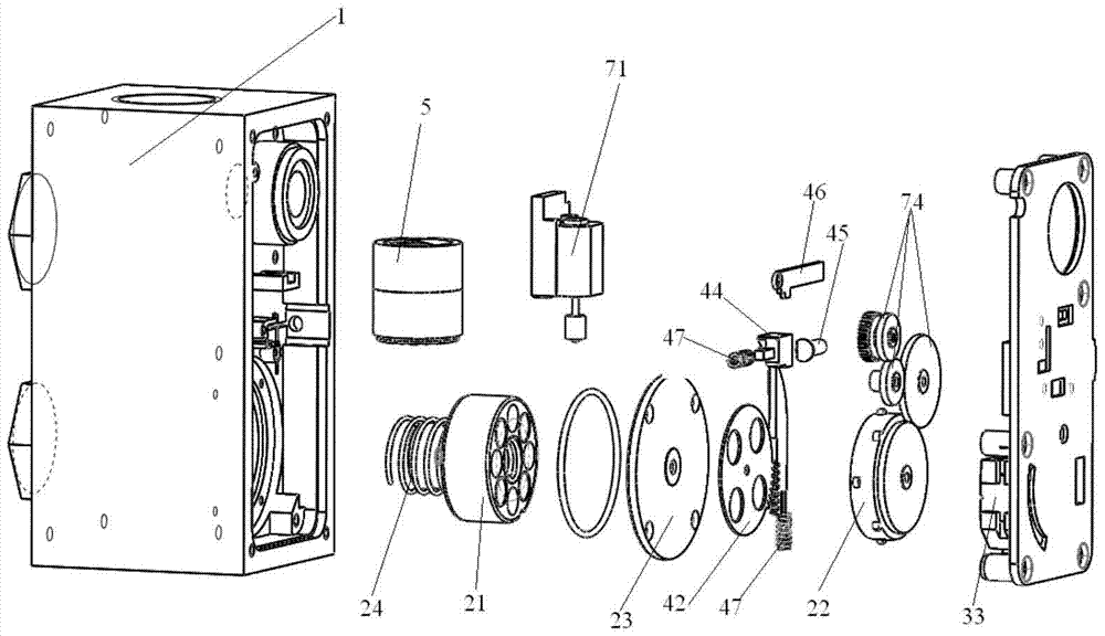
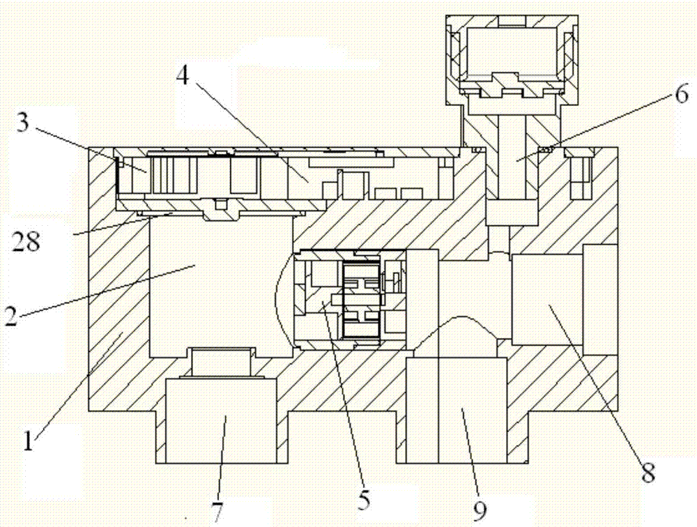
[0035] figure 1 with figure 2 Respectively, a schematic diagram and a cross-sectional view of the key components of a pulse-controlled micro-power position feedback bistable electric control valve of the present invention, including a valve body 1, a rotary magnetic switch structure 2, a position detection structure 3, and a magnetic clutch transmission structure 4. Flow sensor 5, pressure sensor 6, bottom inlet 7, side outlet 8, bottom outlet 9,

[0036] The interior of the valve body 1 is divided into two independently sealed chambers by the sealing ring and the moving core cover plate 23: the mechanism chamber and the entire fluid chamber; the fluid chamber is respectively composed of the bottom inlet 7, the action chamber, the flow sensor chamber, the pressure sensor installation port, The si...


PUM


Abstract

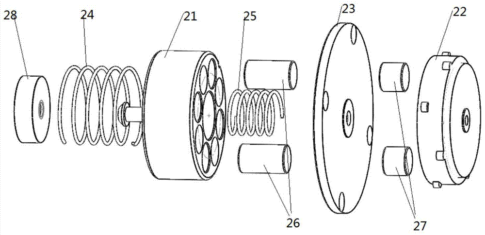
The invention discloses a pulse control type micro-power-consumption position feedback bistable-state electric control valve which comprises a valve body and a bonnet. A rotation magnetic switch structure, a position detecting structure, a magnetic clutch transmission structure and a sensor are disposed in the valve body. The rotation magnetic switch structure comprises a movable core component, a magnet component built in a movable core and a spring component, wherein the movable core component comprises the movable core, a movable core cover plate and a movable core drive plate, the spring component comprises an auxiliary spring disposed on the upper portion of the movable core and a main spring disposed on the lower portion of the movable core, and the magnet component comprises a main magnet disposed inside the movable core and an auxiliary magnet disposed inside the movable core drive part. The pulse control type micro-power-consumption position feedback bistable-state electric control valve has the advantages that the valve meets the requirements of low power consumption, position feedback, single signal control, free of external leakage and various working modes, and the valve is universally applicable to fluid pipeline systems requiring precise control or measuring.

Description

technical field [0001] The invention relates to the technical field of electric control valves, in particular to a pulse-controlled micro-power position feedback bistable electric control valve. Background technique [0002] At present, the electronically controlled valves commonly used in the market include: battery-powered solenoid valves, pulsed bistable solenoid valves, position feedback solenoid valves, and micro-motor-driven bistable solenoid valves. [0003] Battery-powered solenoid valve: double-coil design, the pull-in coil generates a strong enough electromagnetic force to overcome the spring force to make the seal connected to the moving iron core move to the target position; the holding coil generates a relatively small electromagnetic force to The state of the moving iron core remains unchanged; if the coil is not powered, the moving iron core returns to the initial position under the action of the spring force. Reference battery valve products for gas cookers:...

Claims


Application Information

Patent Timeline
Patent Type & Authority Patents(China)
IPC IPC(8): F16K31/06
CPCF16K31/0675F16K37/0083
Inventor 倪仕灿
Owner 上海好芯电子科技有限公司
Learn More