Substrate elevation pin and substrate processing device

A technology of lift pins and substrates, which is applied in transportation and packaging, electrical components, semiconductor/solid-state device manufacturing, etc. It can solve the quality problems of substrate processing products, increase the temperature difference between lift pins 3 and substrates 2, and reduce quality problems. The effect of qualified products

Active Publication Date: 2015-09-09
沈境植
View PDF5 Cites 12 Cited by
  • Summary
  • Abstract
  • Description
  • Claims
  • Application Information

AI Technical Summary

Problems solved by technology

Therefore, a space 4 is generated between the lifting pin 3 and the substrate, causing the heat of the substrate holder 1 to be effectively transferred to the substrate 2 on the upper part of the lifting pin 3
Accordingly, a temperature difference occurs on the substrate 2, which affects the thickness and uniformity of the film quality.
Mo

Method used


Image

  • Substrate elevation pin and substrate processing device
  • Substrate elevation pin and substrate processing device
  • Substrate elevation pin and substrate processing device

Examples


Embodiment Construction

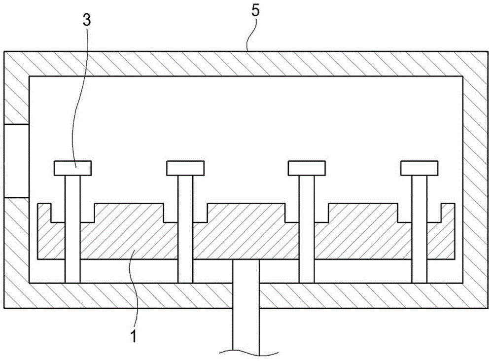
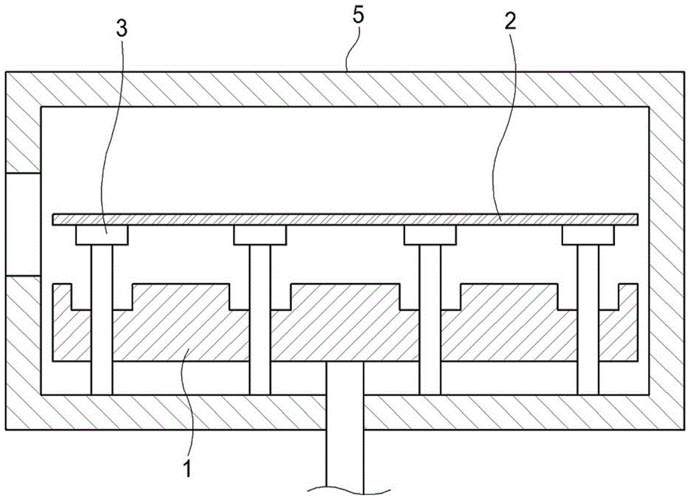
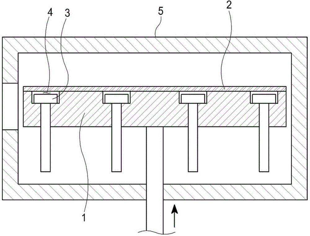
[0043] The substrate lift pin of the present invention is inserted into the vertical through-hole 1b, and the bottom surface of the support groove 1a formed on the upper surface of the substrate holder 1 is narrower, so that it moves up and down relative to the substrate holder 1 as it moves up and down. Place and remove the base plate 2 on the upper part. Different from the traditional lifting pin, the substrate lifting pin of the present invention supports the substrate 2 at its upper part. After the substrate 2 is placed on the upper part of the substrate support 1, it can also be elastically supported so that the upper surface of the lifting pin is in contact with the lower part of the substrate 2. Face close.

[0044] In particular, the substrate lift pin includes a main body portion 10 , a pin portion 20 , and an elastic portion 30 . The main body part 10 is inserted into the through-hole 1b, and when the board|substrate holder 1 ascends, it is hooked by the support gro...


PUM


Abstract

The invention relates to a substrate elevation pin installed on the upper part of the substrate support. The substrate elevation pin enables the upper part surface of the elevation pin to be closely contact with the lower part of the substrate through elastic support when the substrate is installed on the upper part of the substrate and is positioned inside the substrate support. As a result, the heat of the substrate support is effectively transmitted to the substrate on the upper part of the elevation pin to enable the substrate to maintain uniform temperature to prevent the membrane from being abnormal and producing strips.

Description

technical field [0001] The invention relates to a lifting pin for placing a substrate on the upper part of a substrate holder and a substrate processing device including the same. Background technique [0002] Recently, in order to reduce substrate processing steps and production costs, the size of the substrate 2 has become larger, so the number of lift pins 3 that can prevent the substrate 2 from sagging as much as possible has also increased. [0003] Generally speaking, such as Figure 1 to Figure 3 As shown, in the substrate processing process, the existing lifting pin 3 is inserted into the through opening provided in the substrate holder 1 as the substrate holder 1 moves up and down, so that it can move up and down relatively, and the substrate 2 can be placed on and removed from the substrate holder. 1 upper part. [0004] In order to prevent defects on the lower surface of the substrate 2 , after the lift pin 3 of the existing substrate processing device places the...

Claims


Application Information

Patent Timeline
IPC IPC(8): H01L21/677H01L21/683H01L21/68
CPCH01L21/67751H01L21/683H01L21/67098H01L21/68742
Inventor 沈境植
Owner 沈境植
Why Eureka
Try Eureka