Expanding device

A technology of bottom plate and rotating disk, which is applied to the device and coating of the surface coating liquid, which can solve the problems of low glue coating efficiency and complicated operation, and achieve the effect of high spraying efficiency

Active Publication Date: 2015-09-16
SHENZHEN WOER HEAT SHRINKABLE MATERIAL +1
5 Cites 6 Cited by

AI-Extracted Technical Summary

Problems solved by technology

[0003] However, the above-mentioned manual gluing ope...

Method used

[0025] Further, the rotating disk 2 is provided with a number of track grooves 23 distributed in the periphery of the central hole 22 of the rotating disk. The gripper 52 is provided with a guide rail 54 under one end of the cover plate 51 , and the guide rail 54 slides in the track groove 23 . When the drive system 3 drives...

Abstract

The invention discloses an expanding device. The expanding device comprises a base plate, a rotary disc, a driving system, at least three guide wheel sets and a plurality of chucks. A base plate through hole is formed in the base plate. The rotary disc is arranged above the base plate in parallel, a rotary disc center hole is formed in the rotary disc, and the rotary disc center hole is located above the base plate through hole. The guide wheel sets are arranged on the base plate and are evenly distributed on the periphery of the base plate through hole so as to rotate relative to the inner edge of the rotary disc center hole. Each chuck is provided with a cover plate, a clamping handle and a fixing part, wherein the clamping handle is arranged at one end of the cover plate, the fixing part is downwards arranged at the other end of the cover plate, and the fixing part is arranged on the base plate. Compared with the expanding way that a pipe is held with the hand of a worker and a spray head of a gluing device is plugged into the pipe, the expanding device has the advantages that the process of holding the pipe with the hand of the worker during spraying is omitted, expanding is easy and convenient, and spraying efficiency is high.

Application Domain

Technology Topic

Image

  • Expanding device
  • Expanding device
  • Expanding device

Examples

  • Experimental program(1)

Example Embodiment

[0017] In order to describe in detail the technical content, structural features, achieved objectives and effects of the present invention, the following is a detailed description in conjunction with the embodiments and accompanying drawings.
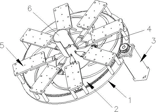
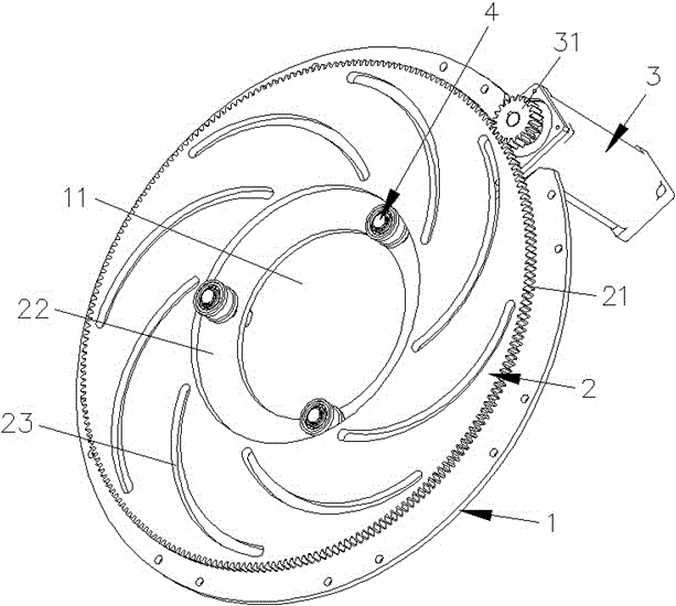
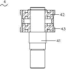
[0018] See figure 1 , The diameter expanding device of the present invention includes a bottom plate 1, a rotating disk 2, a driving system 3, at least three guide wheel sets 4 and a number of chucks 5.
[0019] Please refer figure 1 with figure 2 , The bottom plate 1 is provided with bottom plate perforations 11. In this embodiment, the bottom plate 1 is a circular plate, and the bottom plate perforation 11 is a circular hole.
[0020] The rotating disk 2 is arranged in parallel above the bottom plate 1, the outer periphery of the rotating disk 2 is provided with a rotating gear 21, the center of the rotating disk 2 is provided with a rotating disk center hole 22, and the rotating disk center hole 22 is located above the bottom plate perforation 11. The aperture of the bottom plate perforation 11 is smaller than the aperture of the center hole 22 of the turntable.
[0021] The driving system 3 is provided with a driving gear 31 to cooperate with the rotating gear 21 on the rotating disk 2. The drive system 3 is preferably a drive motor.
[0022] See image 3 , The three guide wheel sets 4 are arranged on the bottom plate 1 and evenly distributed at the periphery of the bottom plate perforation 11 so as to rotate relative to the inner edge of the center hole 22 of the turntable. The three guide wheel sets 4 can form a position limit and guide for the rotating disk 2.
[0023] In this embodiment, the guide wheel set 4 includes a guide wheel shaft 41, a bearing 42 and a guide wheel 43. The guide wheel shaft 41 is evenly distributed at the periphery of the bottom plate perforation 11, a bearing 42 is provided on the guide wheel shaft 41, and a guide wheel 43 is sleeved on the bearing 42. The guide wheel 43 limits and guides the inner edge of the center hole 22 of the turntable.
[0024] See Figure 4 , The chuck 5 has a cover plate 51, a clamping hand 52 and a fixing part 53. The gripper 52 is arranged at one end of the cover plate 51, the other end of the cover plate 51 is connected downwardly to one end of the fixing part 53, and the other end of the fixing part 53 is arranged on the bottom plate 1.
[0025] Furthermore, the rotating disk 2 is provided with a plurality of track grooves 23 distributed on the periphery of the center hole 22 of the rotating disk. The grip 52 is provided with a guide rail 54 below one end of the cover plate 51, and the guide rail 54 slides in the rail groove 23. When the drive system 3 drives the rotating disk 2 to rotate, the guide rail 54 on the chuck 5 slides in the track groove 23 on the rotating disk 52 to achieve the purpose of equal expansion distance of each chuck 5, that is, to ensure that the center of the pipe is clamped The process will not change, so that the chuck 5 can be well positioned and guided.
[0026] When the diameter expanding device of the present invention is working, the diameter expanding device drives the rotating disk 2 to rotate through the driving system 3, and the rotating disk 2 rotates to drive a number of chucks 5 to move outwards with the center hole 22 of the rotating disk as the center, and move outwards on the chucks 5. During the process, the pipe 6 placed on the gripper 52 of the chuck 5 is pulled outwards by the gripper 52 and tightened (the degree of gripping of the pipe can be controlled by controlling the forward and reverse angles of the drive motor) so that the pipe 6 is The mouth becomes larger and the nozzle becomes larger so that the gluing device (not shown in the figure) can easily enter the pipe mouth for gluing operation. Compared with manually holding the pipe and inserting the nozzle of the gluing device into the pipe, spraying is omitted. The process of manually holding the pipe in the process is simple and convenient, and the spraying efficiency is high.
[0027] The present invention is not limited to the above-mentioned specific embodiments, and those skilled in the art can make various changes accordingly, but any changes equivalent or similar to the present invention should be covered within the scope of the claims of the present invention.

PUM

no PUM

Description & Claims & Application Information

We can also present the details of the Description, Claims and Application information to help users get a comprehensive understanding of the technical details of the patent, such as background art, summary of invention, brief description of drawings, description of embodiments, and other original content. On the other hand, users can also determine the specific scope of protection of the technology through the list of claims; as well as understand the changes in the life cycle of the technology with the presentation of the patent timeline. Login to view more.

Similar technology patents

Wall surface spraying apparatus

Owner:临海市天马装璜材料厂

Classification and recommendation of technical efficacy words

Why Eureka
Try Eureka