
Adjusting plate device for sueding machine brush drum

A technology for adjusting the plate and the brush drum, which is applied in the directions of textile and paper making, roughening, and fabric surface trimming, etc., can solve the problems of brush wear, wear of the middle position of the brush roller, uneven grinding, etc., and achieves simple structure, Cost saving, guaranteeing the effect of parallelism

Active Publication Date: 2015-09-16
GUANGDONG RUITUO ENVIRONMENTAL PROTECTION MACHINERY
View PDF4 Cites 3 Cited by
  • Summary
  • Abstract
  • Description
  • Claims
  • Application Information

AI Technical Summary

Problems solved by technology

[0004] Through use, it is known that after the sanding machine has been running for a period of time, the brushes of the brush roller will be worn and uneven. In this way, of course, one of the ways is to replace the new brush roller, and there is also a way to save costs. The best way is to trim the brush of the brush roller, but the diameter of the brush roller will become smaller after trimming. The traditional adjustment plate device can solve the distance adjustment problem by adjusting the distance from the brush roller, but there are still many There are problems, mainly as follows: First, the traditional adjustment plate device is simply adjusted by two positions at both ends. Since the span of the adjustment plate is relatively long, the middle position is free, and the middle position of the adjustment plate will definitely bend; the second is the brush The middle position of the roller is relatively worn, and the diameter of the middle position of the trimmed brush roller is different from that of the brush rollers at both ends; the third is the diameter of each brush roller of the brush drum after use, especially after trimming is different
In this way, the sanding will be uneven, which will seriously affect the quality of cloth sanding.

Method used


Image

  • Adjusting plate device for sueding machine brush drum
  • Adjusting plate device for sueding machine brush drum
  • Adjusting plate device for sueding machine brush drum

Examples


Embodiment Construction

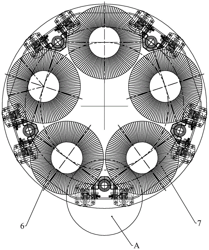
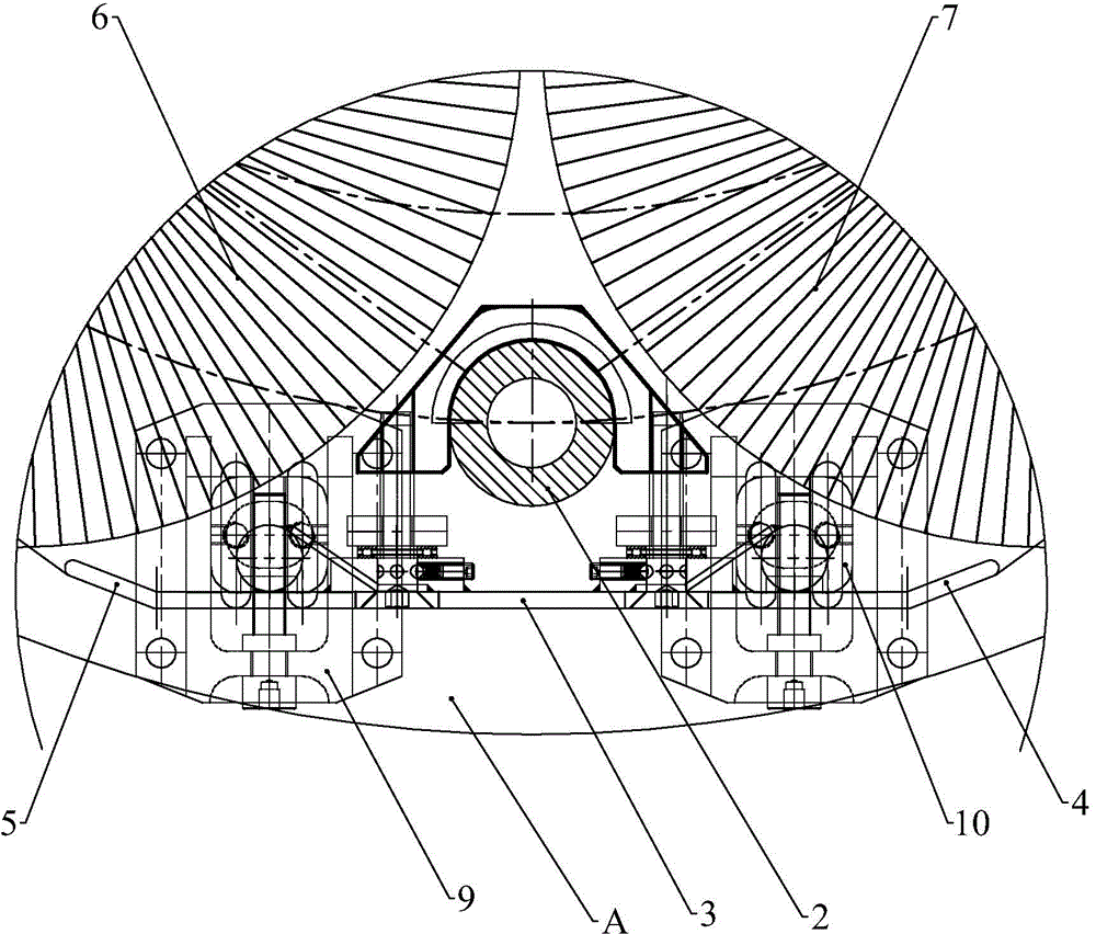
[0024] refer to Figure 1 to Figure 7 , this embodiment includes an adjustment plate 1, a support rod 2, and support seats at left and right ends; the adjustment plate has an opening portion 3, a front guide portion 4 and a rear guide portion 5, and the front guide portion and the rear guide portion are all bent inward and its bending angle is consistent with the tangent angle direction of the adjacent brush rollers 6 and 7; the support seat includes a support plate 8, an adjustment base plate 9 and an adjustment block 10; the adjustment base plate is fixed on the support plate, and the adjustment base plate There are waist-shaped holes 11 in the upper and lower directions, and the adjustment block forms the adjustment installation structure of the adjustment plate up and down through the adjustment bolts and the waist-shaped holes of the adjustment base plate; the adjustment block has waist-shaped holes 12 in the front and rear directions, and the two ends of the adjustment pl...


PUM


Abstract

The invention relates to an adjusting plate device for a sueding machine brush drum, which comprises an adjusting plate, a support rod and support seats at the left and right ends; the adjusting plate has a spreading part, a front guide part and a rear guide part; the front guide part and the rear guide part are both bent inwards, and the bending angles of the front guide part and the rear guide part are respectively consistent with the direction of the tangent line of the adjacent brush roll; the support seat comprises a support disk, an adjusting base plate and an adjusting block; the adjusting base plate is fixed on the support disk, the adjusting block passes through an adjusting bolt and a waist-shaped hole in the vertical direction of the adjusting base plate to form a vertical adjusting mounting structure of the adjusting plate; two bearings at the end part of the adjusting plate are respectively arranged in the waist-shaped holes in the front and back directions of two adjusting blocks by adjusting bolts to form an adjusting plate angle adjusting mounting structure; the adjusting plate is connected with the support rod by adjusting bolts I arranged at the middle front part and the middle rear part to form an adjusting plate bending adjusting mounting structure. The adjusting plate device has the advantages of being capable of adjusting in an omnibearing way, simple in structure and saving in cost.

Description

technical field [0001] The invention relates to an adjustment plate device for a brush drum of a sanding machine. Background technique [0002] The brush drum of the sanding machine is the core part of the whole sanding machine. The brush drum is mainly composed of a brush roller and an adjustment plate. The brush roller is used for sanding. The cloth of the brush roller can be smoother; the adjustment plate is also used to control the contact area between the cloth and the brush roller and the pressure between the cloth and the brush roller. The sanding effect plays a key role. [0003] The traditional adjusting plate device only supports the adjusting plate at both ends, and can only adjust the distance between the adjusting plate and the brush roller at both ends. [0004] Through use, it is known that after the sanding machine has been running for a period of time, the brushes of the brush roller will be worn and uneven. In this way, of course, one of the ways is to re...

Claims


Application Information

Patent Timeline
IPC IPC(8): D06C11/00
CPCD06C11/00
Inventor 许艳萍戴立国林卓峰王刚容文劲
Owner GUANGDONG RUITUO ENVIRONMENTAL PROTECTION MACHINERY
Learn More