In-section multi-cluster fracturing slide sleeve

A technology for fracturing sliding sleeves and sliding sleeves, which is applied in the fields of production fluids, wellbore/well components, and earth-moving drilling and mining, etc., can solve the problems of limited number of reformation series, affecting construction scale, and running tools of production in the later stage of reformation effect.

Active Publication Date: 2015-09-16
PETROCHINA CO LTD
View PDF17 Cites 6 Cited by
  • Summary
  • Abstract
  • Description
  • Claims
  • Application Information

AI Technical Summary

Problems solved by technology

The sliding sleeve is designed with a step difference, and the internal diameter changes from small to large from bottom to top. Due to the limitation of the design size of the wellhead, wellbore, construction pipe string and tools, the number of transformation stages is limited, and the gradually reduced pipe diameter will affect the construction scale. Transformation effect, post-production and operation tool downloading issues

Method used


Image

  • In-section multi-cluster fracturing slide sleeve
  • In-section multi-cluster fracturing slide sleeve

Examples


Embodiment 1

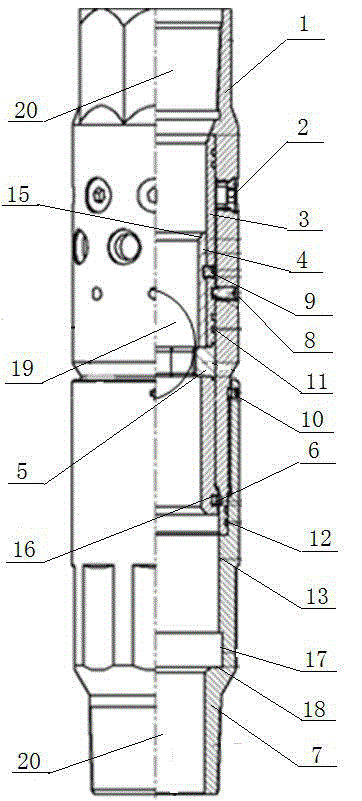
[0022] This embodiment provides a multi-cluster fracturing sliding sleeve in a section, such as figure 1 As shown, it includes an outer cylinder 1 and a lower joint 7, the external thread at the lower end of the outer cylinder 1 is screwed with the inner thread at the upper end of the lower joint 7, a plurality of nozzles 2 are arranged on the wall of the outer cylinder 1, and a sliding sleeve 3 is installed inside the outer cylinder 1 , the shear pin 8 passes through the outer cylinder 1 and the sliding sleeve 3 to fix the two; the ball seat 5 is installed in the middle of the sliding sleeve 3, and the inner side of the sliding sleeve 3 is provided with a throttling tube 4, and the connecting pin 9 passes through the sliding sleeve in turn. The sleeve 3 and the throttling tube 4 fix the two, and the bottom end of the throttle tube 4 acts on the ball seat 5; the inside of the lower joint 7 is provided with a sliding sleeve expanding section 13;

[0023] The ball seat 5 is made...

Embodiment 2

[0028] On the basis of Embodiment 1, in this embodiment, the upper inner side of the outer cylinder 1 is provided with a sliding sleeve upper limit platform 15 , and the upper end of the sliding sleeve 3 collides with the sliding sleeve upper limit platform 15 . The lower joint 7 is provided with a sliding sleeve lower limiting platform 18, and the sliding sleeve lower limiting platform 18 is located at the lower part of the circlip release groove 17.

[0029] The lower part of the outer wall of the sliding sleeve 3 is provided with a circlip groove 16, and a circlip 6 is installed in the circlip groove 16;

[0030] The upper limit platform 15 of the sliding sleeve and the lower limiting platform 18 of the sliding sleeve limit the range of motion of the sliding sleeve 3. When the sliding sleeve 3 moves downward to the position of the lower limiting platform 18 of the sliding sleeve, the circlip 6 installed in the circlip groove 16 Launch this moment, enter jump ring release gr...

Embodiment 3

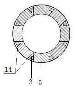
[0032] Such as figure 2 shown, combined with figure 1 , in this embodiment, there are eight hollow ball seat holes 14, which are evenly distributed in the middle of the sliding sleeve 3 in the circumferential direction; the ball seat 5 is composed of eight independent sliders, and the eight independent sliders are respectively located in the eight hollow ball seat holes. 14, and the thickness of the slider is greater than the depth of the hollow ball seat hole 14.

[0033] At the initial position, one end of the eight independent sliders close to the outer cylinder 1 is against the inner side of the outer cylinder 1, and the other end located inside will exceed the innermost side of the sliding sleeve 3 side. At this time, if there is a sealing ball 19 coming down, It will be directly blocked by the ball seat 5, so that the sealing ball 19 sits on the ball seat 5. When the sliding sleeve 3 moves downward, the end of the slider close to the outer cylinder 1 enters the expandi...


PUM


Abstract

The invention discloses an in-section multi-cluster fracturing slide sleeve, which comprises an outer tube, a spray nozzle, a slide sleeve, a throttle tube, a ball seat, a clamp spring, a lower joint and the like, wherein the spray nozzle is bonded and arranged on the outer tube; the slide sleeve is arranged in the outer tube, is connected with the outer tube through a shearing pin, and is sealed through a slide sleeve sealing ring; the ball seat is arranged in a position of a ball seat hole formed in the middle part of the slide sleeve; the clamp spring is arranged at the tail of the slide sleeve; the throttle tube is arranged in the slide sleeve and is fixed with the slide sleeve through a connecting pin; and the lower joint and the outer tube are connected through screw threads, are fixed through anti-falling pins and are sealed through a lower joint sealing ring. The in-section multi-cluster fracturing slide sleeve has the advantages that the slide sleeve opening and ball passing actions are realized through diameter reduction and expansion of the ball seat; a plurality of fractures can be opened through one ball; the in-section multi-cluster fracturing in an open-hole horizontal well can be realized; the oil drainage area of the horizontal well can be effectively increased; the initial output and the final recovery ratio are improved; meanwhile, through the design of throttle fracture holes in the outer tube, fixed-point crack positioning can be realized; the influence of near-well zone stress (due to drilling) is reduced; the pressure division probability is increased; and the fracturing effect is further improved.

Description

technical field [0001] The invention relates to a ball-pitching sliding sleeve, in particular to a sliding sleeve for multi-cluster fracturing in a low-permeability open-hole horizontal well, in particular to a sliding sleeve for multi-cluster fracturing in a segment. Background technique [0002] Studies have shown that for horizontal wells in low-permeability oil and gas fields, due to multiple constraints such as reservoir conditions, injection-production well pattern, and fracturing technology, the effect of increasing production by simply increasing the fracture length is not obvious, and it is difficult to achieve such a well through conventional fracturing technology transformation. Commercial value of oil and gas reservoirs. For such wells, "volume fracturing" is required, that is, while one or more main fractures are formed, fractures are formed through the application of staged multi-cluster fracturing, high displacement, large fluid volume, low viscosity fluid and...

Claims


Application Information

Patent Timeline
Patent Type & Authority Applications(China)
IPC IPC(8): E21B43/26
Inventor 赵粉霞邵媛蒙鑫郭思文赵广民冯长青胡相君赵敏琦张丽娟
Owner PETROCHINA CO LTD
Why Eureka
Try Eureka