Engine Output Shaft Connecting Device and Its Application Separate Hydraulic Power Unit

A technology of engine output and shaft connection device, applied in the field of engine and hydraulic power, can solve the problems of difficult installation of connecting shaft, limited construction conditions, time-consuming and labor-intensive, etc., to ensure the stability of equipment operation, reduce time and strength, reduce The effect of construction costs

Active Publication Date: 2017-04-05
CHANGLAN CABLE ACCESSORIES
View PDF6 Cites 0 Cited by
  • Summary
  • Abstract
  • Description
  • Claims
  • Application Information

AI Technical Summary

Problems solved by technology

[0002] Small industrial engines usually do not use fixed connections. An engine can usually be connected to replace different drive components for multiple purposes. During the connection setting process of the engine, a connecting shaft will be used to connect the output shaft of the engine and the input shaft of the drive components. It is difficult to install the connecting shaft in the process of connecting the engine or driving parts. During the installation process, the most important thing is the centering of the connecting shaft. The connecting shaft is usually fixedly connected to one end of the shaft part, and the other end is suspended. In this way, the axis of the connecting shaft is often not on the same shaft axis as the shaft parts connected at both ends. Whether it is the hoisting of the engine or the lifting of the driving parts, it is time-consuming and labor-intensive. It is necessary to quickly connect the connecting shaft to one of the shaft parts. After the coaxial centering is set, the other end can quickly achieve positioning and connection assembly. If the coaxial centering is not realized during the installation process, the shaft parts will wear out during the working process of the drive components, and the power loss of the equipment will be relatively large, which will affect normal work
[0003] Taking the hydraulic power station in the process of electric power construction as an example, in the complex field construction environment, the handling of the hydraulic power station with a large weight and volume is quite difficult, especially in emergency rescue projects, where various terrain environments may appear, The handling of the hydraulic power unit has had a great impact on construction and rescue, and seriously affects the speed and progress of construction and rescue. Therefore, the engine and hydraulic power unit will be transported separately and connected and assembled at the construction site
But often in the connection and assembly process of the engine, due to limited construction conditions, the quick connection assembly of the engine is more difficult

Method used


Image

  • Engine Output Shaft Connecting Device and Its Application Separate Hydraulic Power Unit
  • Engine Output Shaft Connecting Device and Its Application Separate Hydraulic Power Unit
  • Engine Output Shaft Connecting Device and Its Application Separate Hydraulic Power Unit

Examples


Embodiment 1

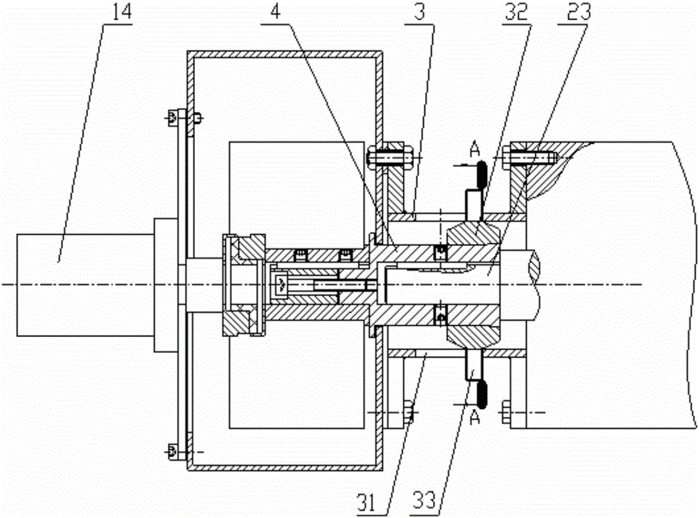
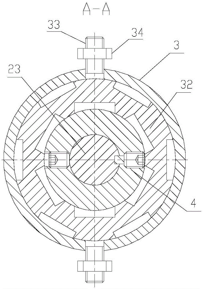
[0029] see figure 1 and figure 2 , a connection device for an engine output shaft, comprising a spacer ring 3, a positioning sleeve 32 and an extension shaft 4; the two ends of the spacer ring 3 are provided with a flange structure, and are fixedly connected to the fixed box wall of the driving part or the shaft of the engine through the flange connection Between the end faces, the engine and drive components are fixed together.

[0030] The extension shaft 4 is arranged in the spacer ring 3 and is coaxial with the spacer ring 3. One end of the extension shaft 4 is coaxially connected with the input shaft of the driving part (hydraulic pump 14), and the other end is a hollow shaft, which is sleeved on the engine through a key connection. On the output shaft 23 ; the positioning sleeve 32 is arranged between the spacer ring 3 and the extension shaft 4 and is coaxial with the spacer ring 3 . Specifically, the diameter of the outer ring of the positioning sleeve 32 is equal to...

Embodiment 2

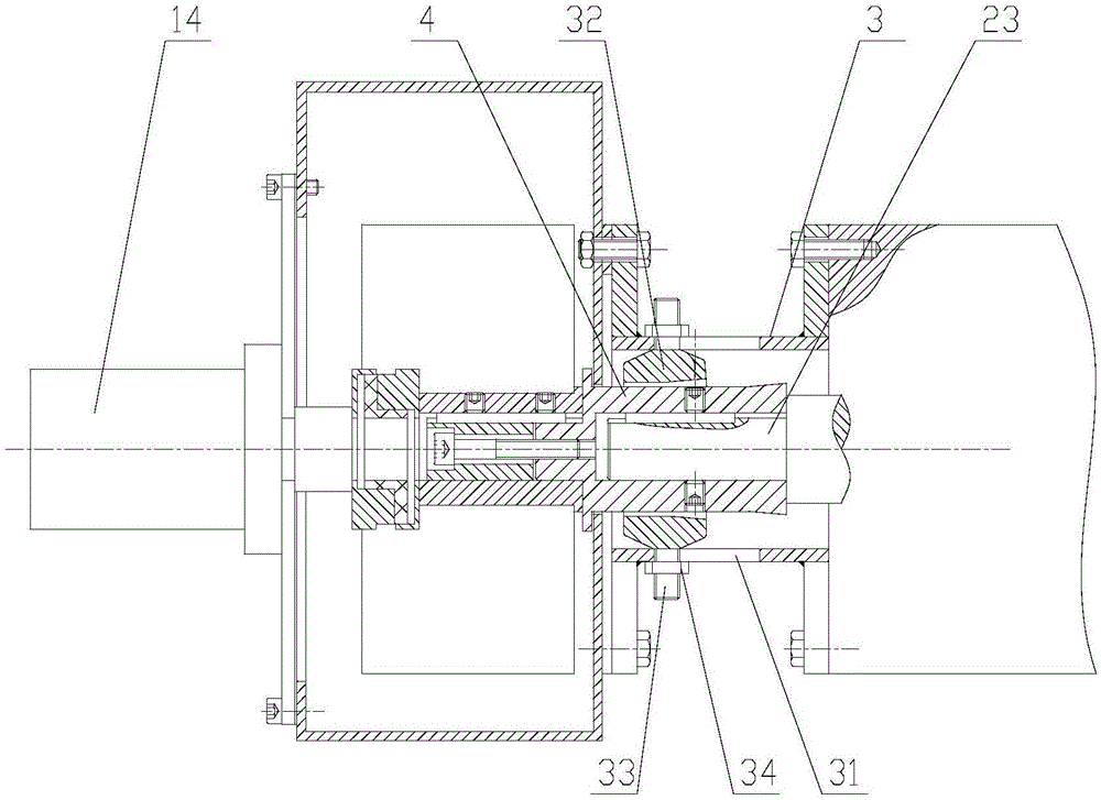
[0036] In this embodiment, on the basis of Embodiment 1, Embodiment 1 is applied to a separate hydraulic power station, such as Figure 4 and Figure 5 As shown, the engine device 2 of the hydraulic power station is connected to the hydraulic pump of the hydraulic power unit 1 through the engine output shaft connection device disclosed in Embodiment 1, and a spacer ring 3 is provided between the hydraulic power unit 1 and the engine unit 2, and the spacer ring The two ends of 3 are respectively connected with the hydraulic power pack box wall 11 and the engine shaft end face 21 through flanges, one end of the extension shaft 4 of the spacer ring 3 is fixedly connected with the hydraulic pump input shaft of the hydraulic power pack 1, and the other end is hollow The shaft section is socketed with the engine output shaft 23 through a key connection (spline or flat key), and a positioning sleeve is provided between the spacer ring 3 and the extension shaft 4 (see embodiment 1 for t...


PUM


Abstract

The invention discloses an engine output shaft connection device, which comprises a spacer ring, a positioning sleeve and a lengthening shaft, wherein one end of the spacer ring is fixedly arranged on a fixed box wall of a driving component or a shaft end surface of an engine, and the other end of the spacer ring is detachably connected with another component; the lengthening shaft is coaxially arranged in the spacer ring, one end of the lengthening shaft is coaxially fixedly connected with an engine output shaft or the input shaft of a driving component, and the other end of the lengthening shaft is a hollow shaft and is sheathed on the other shaft part by key connection; the positioning sleeve is coaxially arranged between the spacer ring and the lengthening shaft; the diameter of the outer ring of the positioning sleeve is equal to the internal diameter of the spacer ring; the positioning sleeve is sheathed on the lengthening shaft; the tail end part of the outer ring of the hollow shaft section of the lengthening shaft is a cone of which the diameter gradually increases; the maximum internal diameter of the positioning sleeve is not greater than the maximum diameter of the hollow shaft section of the lengthening shaft. The quick alignment of the lengthening shaft and the engine shaft is realized by the positioning sleeve, the positioning sleeve and the lengthening shaft are separated after the engine finishes being installed, equipment is free from additional power loss, and the use efficiency of various types of hydraulic construction equipment can be further improved.

Description

technical field [0001] The invention belongs to the field of engine technology and hydraulic power technology, and in particular relates to an engine output shaft connection device and a separate hydraulic power station for its application. Background technique [0002] Small industrial engines usually do not use fixed connections. An engine can usually be connected to replace different drive components for multiple purposes. During the connection setting process of the engine, a connecting shaft will be used to connect the output shaft of the engine and the input shaft of the drive components. It is difficult to install the connecting shaft in the process of connecting the engine or driving parts. During the installation process, the most important thing is the centering of the connecting shaft. The connecting shaft is usually fixedly connected to one end of the shaft part, and the other end is suspended. In this way, the axis of the connecting shaft is often not on the sam...

Claims


Application Information

Patent Timeline
Patent Type & Authority Patents(China)
IPC IPC(8): F02B65/00
Inventor 贺智涛潘建庭陈彦廷李瀚儒许继葵李绍斌叶波
Owner CHANGLAN CABLE ACCESSORIES
Why Eureka
Try Eureka