Shaft spring

A shaft spring and spindle technology, applied to springs, springs/shock absorbers, springs made of plastic materials, etc., can solve the problems of increased number of components, increased cost, and complex structure, and achieve low cost and reasonable assembly , to achieve the effect of simplifying the structure

Active Publication Date: 2015-09-16
NITTA CHEM IND PROD CO LTD
View PDF8 Cites 9 Cited by
  • Summary
  • Abstract
  • Description
  • Claims
  • Application Information

AI Technical Summary

Problems solved by technology

[0009] However, in the scheme shown in Japanese Patent Laid-Open No. 2003-341511, since the control system of the air spring is required in addition to the elastic layer, not only will the number of parts increase and the cost will increase, but also because the air spring is fixed on the upper part of the main shaft. spring, thus also complicating the structure
In addition, as shown in Japanese Unexamined Patent Application Publication No. 2006-057746, in the case where components interfere with each other, there is a problem of noise generated during interference, and it is difficult to obtain long-term stable characteristics.

Method used


Image

  • Shaft spring
  • Shaft spring
  • Shaft spring

Examples


Embodiment Construction

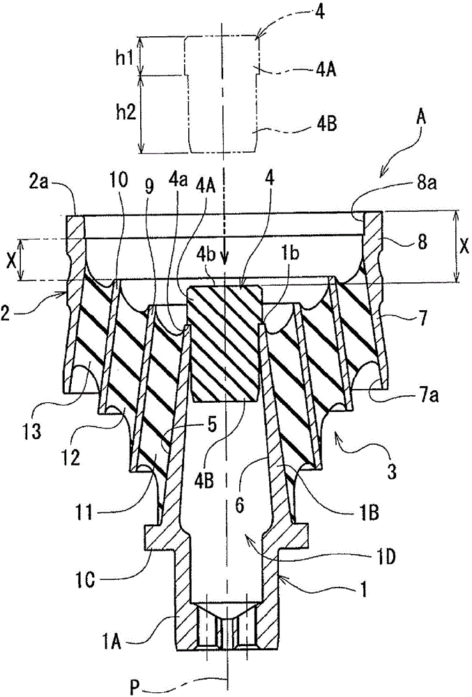
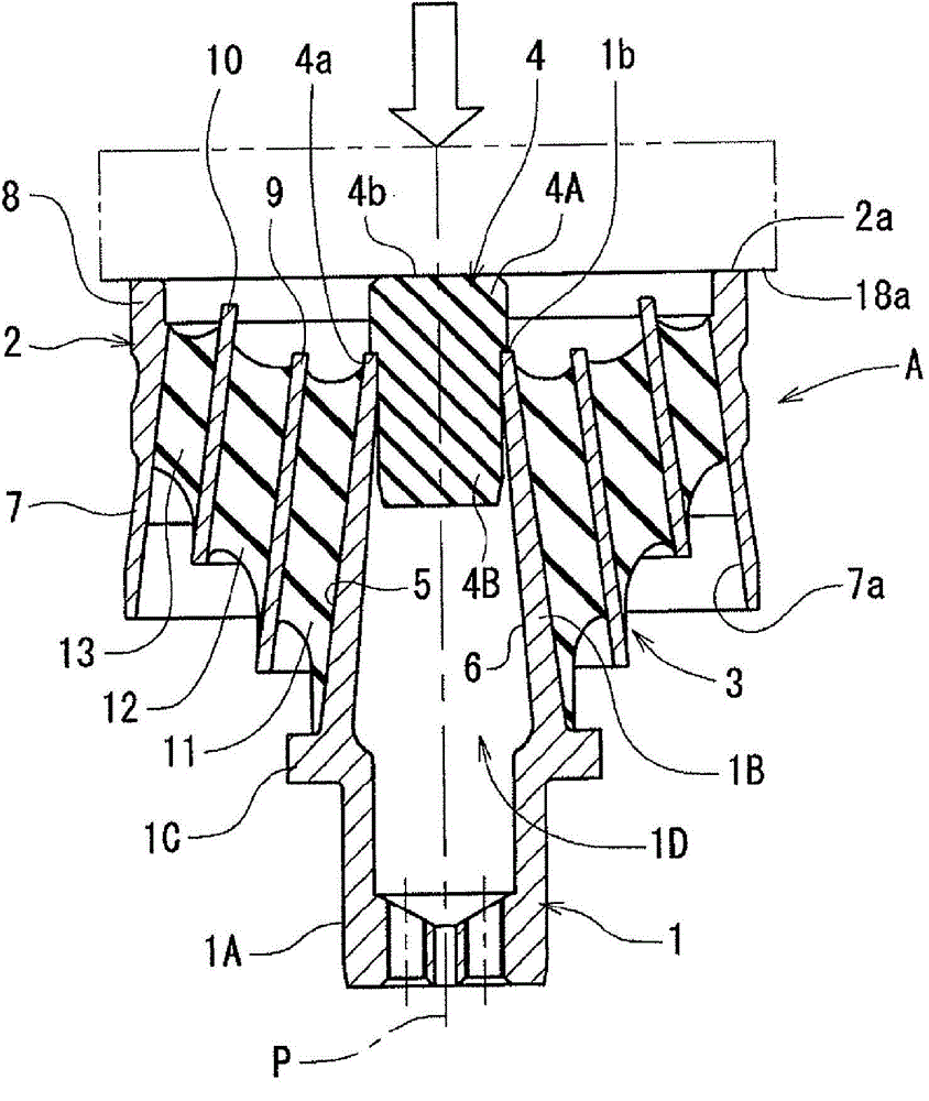
[0033] Next, embodiments of the shaft spring of the present invention will be described with reference to the drawings. In addition, if figure 1 As shown, since the outer cylinder 2 is often used in an upper position with respect to the main shaft 1, this state is referred to as an upright state, and up, down, left, and right are defined in this upright state.

[0034] According to the present invention, if figure 1 As shown, the shaft spring A includes: a main shaft 1; an outer cylinder 2; an elastic part 3 interposed between the main shaft 1 and the outer cylinder 2; like figure 1 As shown, the shaft spring A is often used in an upright state with the main shaft 1 positioned below the outer cylinder 2, but it is not limited thereto.

[0035] The main shaft 1 has an axis P and is circular when viewed from the direction of the axis P. The main shaft 1 includes: a support portion 1A at the lower end, which is supported by the side of the trolley; an upper main body portio...


PUM


Abstract

The invention provides a shaft spring which, compared with the prior art, is not limited by changing of weight on the spring during emergency break at full commission, provides high riding comfort, reducing non-linear characteristics of shaking, preventing increasing of parts number and structural complexity due to non-linear characteristics and is excellent in endurance. The shaft spring comprises a main shaft, an outer cylinder which is configured in such a manner of, when viewed from the axis center of a main shaft, enclosing the main shaft, and an elastic portion which is formed in such a manner of laminating alternatively with radial inner and outer directions of an intermediate hard cylinder and the axis center of an elastic layer and installing between the main shaft and the outer cylinder. The main shaft is provided with blocks made of elastic materials, and the blocks approach to each other with the main shaft on the axis center direction of the outer cylinder with preset amount. A body fixed outside the outer cylinder abuts against the blocks, and the blocks are detachably installed on the main shaft.

Description

technical field [0001] The present invention relates to a shaft spring device mainly used in railway vehicles, in particular to a shaft spring with an elastic part interposed between a main shaft and an outer cylinder, wherein, when viewed from the direction of the shaft center of the main shaft, the outside of the outer cylinder is The side is arranged in a state surrounding the main shaft, and the elastic part is formed by alternately laminating the middle hard tube and the elastic layer in the radially inner and outer directions of the shaft center. Background technique [0002] As an example of using such a shaft spring, there are many examples of applying it to a bogie for railway vehicles. For example, Japanese Patent Application Publication No. 2009-115156 (refer to image 3 ), the railway trolley 29 is used as a unit that suspends and supports the axle box 27 on the trolley frame 28, wherein the axle box 27 is used to support the axle 26 of the wheel 25. [0003] Ho...

Claims


Application Information

Patent Timeline
Patent Type & Authority Applications(China)
IPC IPC(8): F16F15/08F16F1/38
CPCB61F5/30F16F1/3814F16F1/3842F16F15/08
Inventor 杉本宪一
Owner NITTA CHEM IND PROD CO LTD
Why Eureka
Try Eureka