Total timing precision calibration device of integrated circuit test system

A timing accuracy and testing system technology, applied in the field of calibration systems, can solve problems such as the lack of quantitative measurement methods and devices, the digital timing error of the tested integrated circuit, and the inability to guarantee the reliability of the tested integrated circuit, etc., to achieve accurate evaluation of high-speed performance , the effect of solving the calibration problem

Active Publication Date: 2015-09-16
NO 709 RES INST OF CHINA SHIPBUILDING IND CORP
View PDF3 Cites 8 Cited by
  • Summary
  • Abstract
  • Description
  • Claims
  • Application Information

AI Technical Summary

Problems solved by technology

[0003] The technical index of the total timing accuracy of the integrated circuit test system is usually at the picosecond level. When the integrated circuit test system drives or measures a certain signal, its driving edge or comparison edge deviates from the expected time, which will directly lead to the digital timing of the tested integrated circuit. If the test result of the test system is not reliable, the reliability of the integrated circuit under test cannot be guaranteed.
[0004] At present, in China, only the main time base frequency of the test system is measured, or methods such as eye diagram analysis are used to indirectly verify or qualitatively analyze this indicator, and there is no quantitative measurement method and device

Method used


Image

  • Total timing precision calibration device of integrated circuit test system
  • Total timing precision calibration device of integrated circuit test system
  • Total timing precision calibration device of integrated circuit test system

Examples


Embodiment Construction

[0023] In order to make the purpose, technical solutions and advantages of the present invention more clearly understood, the present invention will be described in further detail below with reference to the accompanying drawings and embodiments. It should be understood that the specific embodiments described herein are only for explaining the present invention, not for The invention is limited.

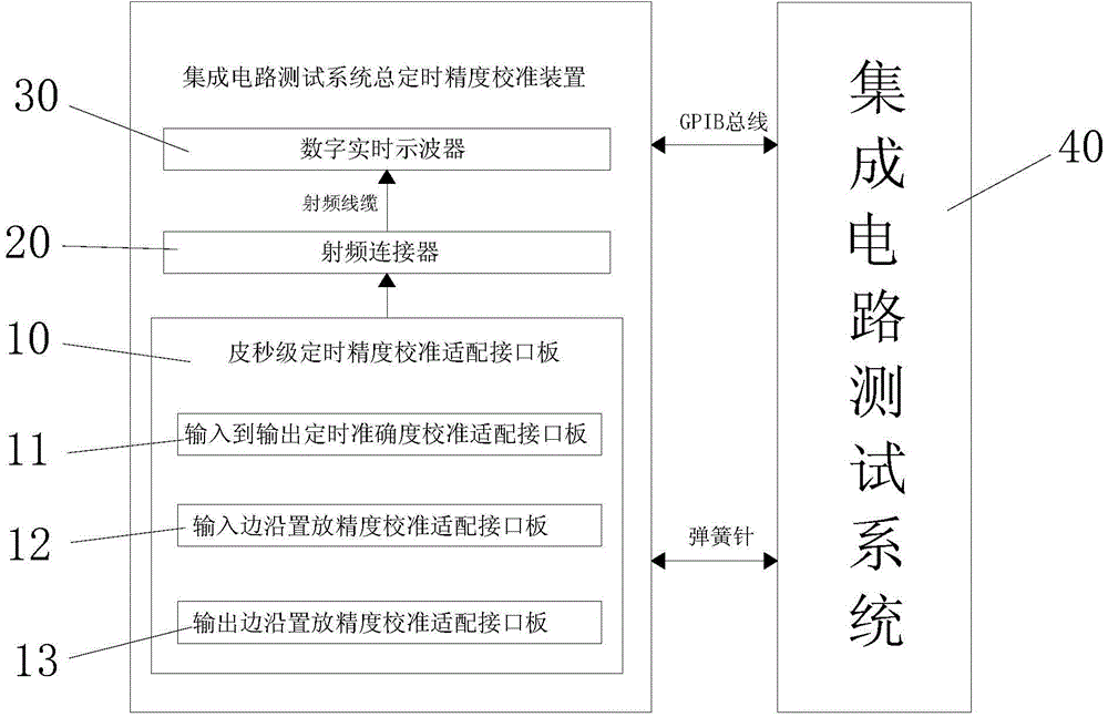
[0024] like figure 1 As shown, the present invention provides a total timing accuracy calibration device for an integrated circuit test system, including a picosecond timing accuracy calibration adapter interface board 10, a radio frequency connector 20, and a digital real-time oscilloscope 30;

[0025] The picosecond-level timing accuracy calibration adapter interface board 10 is connected to the integrated circuit test system 40, the radio frequency connector 20 is arranged on the picosecond-level timing accuracy calibration adapter interface board 10, and the radio frequency conne...


PUM


Abstract

The invention provides a total timing precision calibration device of an integrated circuit test system. The total timing precision calibration device comprises picoseconds-grade timing precision calibration adaption interface boards, a radio-frequency connector and a digital real-time oscilloscope; and a signal channel of the picoseconds-grade timing precision calibration adaption interface boards is connected with a test channel of the integrated circuit test system, the radio-frequency connector is disposed on the picoseconds-grade timing precision calibration adaption interface boards and is in a butt joint with the test channel of the integrated circuit test system through the picoseconds-grade timing precision calibration adaption interface boards, the radio-frequency connector is connected with a test channel of the digital real-time oscilloscope through a radio-frequency cable, and the digital real-time oscilloscope is in communication with the integrated circuit test system through a GPIB bus. An input-to-output timing accuracy calibration adaption interface plate, an input edge placing precision calibration adaption interface plate and an output edge placing precision calibration adaption interface plate are designed, and the radio-frequency connector and the radio-frequency cable are adopted to be connected with the digital real-time oscilloscope, so measurement for total timing precision of the integrated circuit test system is achieved.

Description

technical field [0001] The invention relates to a calibration system, in particular to a total timing precision calibration device of an integrated circuit test system. Background technique [0002] In the application of high-speed integrated circuit test, the requirements for the time parameter of the test system are extremely strict. The total timing accuracy of the integrated circuit test system is a key time parameter that reflects whether the signal driving edge or comparison edge provided by the test system is within the expected time range, and whether the relative time between each signal is accurate. Only by comprehensively and accurately analyzing this core time parameter of the test system can the performance and stability of the test system be guaranteed. [0003] The technical index of the total timing accuracy of the integrated circuit test system is usually in the picosecond level. When the integrated circuit test system drives or measures a signal, its drivi...

Claims


Application Information

Patent Timeline
Patent Type & Authority Applications(China)
IPC IPC(8): G01R35/00
Inventor 刘倩张明虎胡勇
Owner NO 709 RES INST OF CHINA SHIPBUILDING IND CORP
Why Eureka
Try Eureka