Signal redisplay method and system of spliced wall

A splicing wall and signal display technology, applied in CCTV systems, components of TV systems, image communication, etc., can solve the problems of affecting processor image output, large signal access, network bottlenecks, etc., to reduce network bottlenecks effect of the problem

Active Publication Date: 2015-09-16
GUANGDONG VTRON TECH CO LTD
View PDF4 Cites 6 Cited by
  • Summary
  • Abstract
  • Description
  • Claims
  • Application Information

AI Technical Summary

Problems solved by technology

In the splicing wall visual control display system, due to the high resolution of the display wall, the large amount of signal access, and the complex configuration, it is necessary to display high-definition echoes when performing splicing wall signal content echo and signal preview display on the configuration operation device Content requires high-performance and high-bandwidth system environment support, and the video wall processor needs to output high-definition echo content, which not only brings network bottlenecks, but also may affect the image output of the processor, which cannot be used in the video wall environment. accepted

Method used


Image

  • Signal redisplay method and system of spliced wall
  • Signal redisplay method and system of spliced wall
  • Signal redisplay method and system of spliced wall

Examples


Embodiment 2

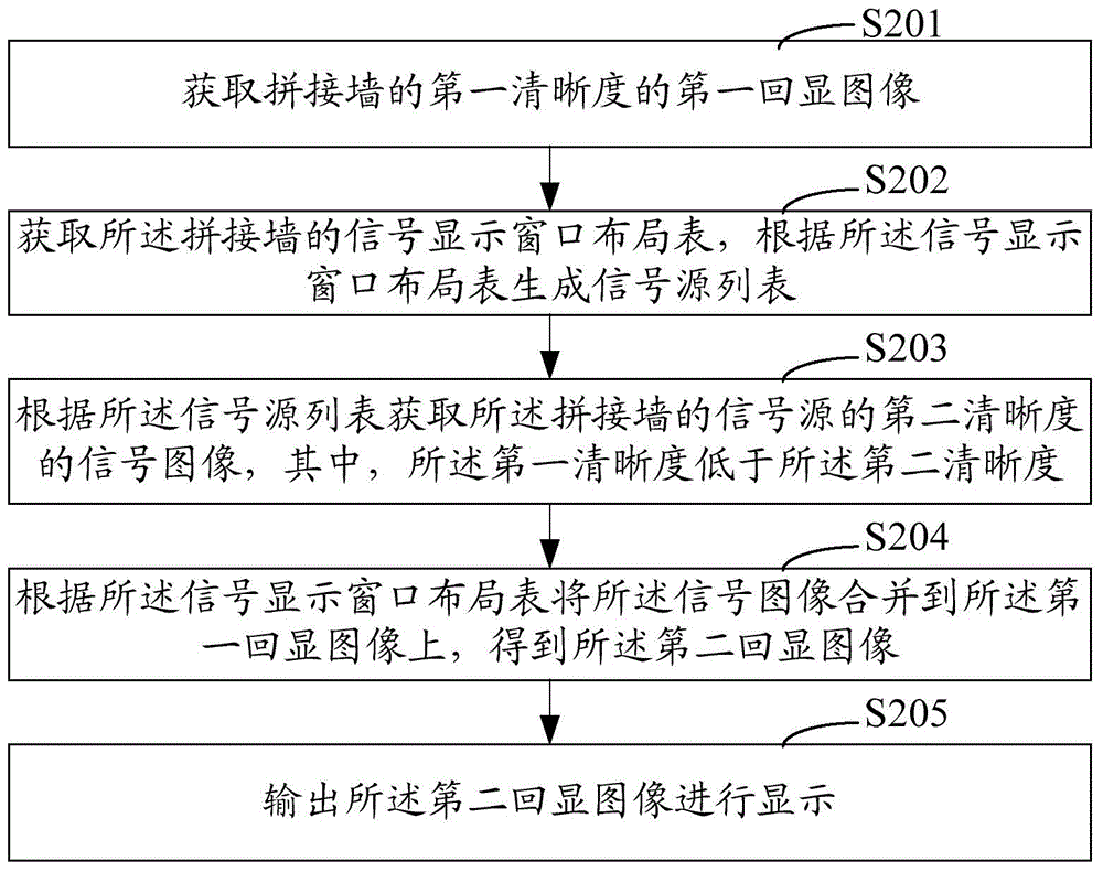
[0045] see figure 2 As shown, it is a schematic flowchart of Embodiment 2 of the video wall signal echo method of the present invention. In this embodiment, the main difference from the first embodiment above is that it takes into account the need to acquire the signal image and merge the signal image into the first echo image, that is to say, it is necessary to know the current signal source information of the video wall (what signal sources are there) and the position information of the display windows opened by these signal sources on the splicer. For this reason, in this embodiment, the step of obtaining the signal display window layout table of the video wall is added, which can facilitate the video wall The current signal source information and the position information of these signal sources on the display window opened on the splicer.

[0046] Such as figure 2 As shown, the video wall signal echo method in the second embodiment includes the following steps:

[004...

Embodiment 3

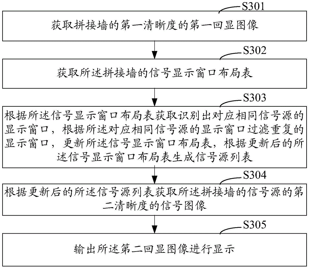
[0057] see image 3 As shown, it is a schematic flowchart of Embodiment 3 of the video wall signal echo method of the present invention. In this embodiment, the main difference from the second embodiment above is that, considering that there may be multiple display windows corresponding to the same signal source in the signal display window layout table initially obtained from the control server, if repeated to When the signal source or the signal preview server obtains the display image, the resource consumption of the signal source or the signal preview server will be increased. For this reason, in the third embodiment, the step of filtering and filtering repeated display windows is added, which can reduce the need for the signal source or signal preview server. Signal preview server resource consumption.

[0058] Such as image 3 As shown, the video wall signal echo method in the third embodiment includes the following steps:

[0059] Step S301: Acquiring the first echo ...

Embodiment 4

[0068] Such as Figure 4 As shown, it is a schematic flowchart of Embodiment 4 of the video wall signal echo method of the present invention. In this embodiment, the main difference from the first embodiment above is that, considering that the initial size of the first echoed image is often inconsistent with the output size of the echoed image, for this reason, in this embodiment, the addition of A step of adjusting the size of the first echoed image to the output size.

[0069] Such as Figure 4 As shown, the video wall signal echo method in Embodiment 4 includes the following steps:

[0070] Step S401: Acquiring the first echo image of the first definition of the video wall;

[0071] Step S402: Obtain the output size of the echoed image, and adjust the size of the first echoed image to the output size;

[0072] The echo image here may refer to the first echo image or the second echo image;

[0073] The adjustment here can refer to zooming in or zooming out, but consider...


PUM


Abstract

The invention relates to a signal redisplay method and system of a spliced wall. The method comprises the steps that a first redisplay image of a first sharpness of the spliced wall is obtained; a signal image of a second sharpness of a signal source of the spliced wall is obtained, and the first sharpness is lower than the second sharpness; the signal image is merged into the first redisplay image to obtain a second redisplay image; and the second redisplay image is output and displayed. According to the technical scheme, the network bottleneck problem caused by transmission of high-sharpness video stream or image content and the problem of resource consumption when the high-sharpness content is processed are effectively solved.

Description

technical field [0001] The present invention relates to the technical field of video wall display, in particular to a video wall signal echo method and system. Background technique [0002] Users use PC (personal computer) to operate directly facing it. The mouse and keyboard are responsible for the input of operation instructions, and the monitor is responsible for output. The interaction with the user is completed through the mouse, keyboard and monitor. result. [0003] The video wall display system is composed of different display units, so the use of the video wall display system is completely different from that of a PC. In the splicing wall visual control display system, due to the high resolution of the display wall, the large amount of signal access, and the complex configuration, it is necessary to display high-definition echoes when performing splicing wall signal content echo and signal preview display on the configuration operation device Content requires high...

Claims


Application Information

Patent Timeline
Patent Type & Authority Applications(China)
IPC IPC(8): H04N7/18H04N5/262
Inventor 廖天素陈先志余雪晨
Owner GUANGDONG VTRON TECH CO LTD
Why Eureka
Try Eureka